Register now to gain access to all of our features. Once registered and logged in, you will be able to contribute to this site by submitting your own content or replying to existing content. You'll be able to customize your profile, receive reputation points as a reward for submitting content, while also communicating with other members via your own private inbox, plus much more! This message will be removed once you have signed in.

tomasbj
Members-
Content count
33 -
Joined
-
Last visited
Posts posted by tomasbj
-
-
On 14/2/2019 at 10:36 AM, Admin said:I recommend this broadband antenna...

HI mate. Do you have this model in CST? It is awesome! I would like to try to make it with Circular Pol. Thanks
-
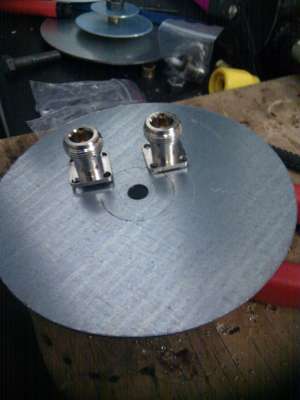
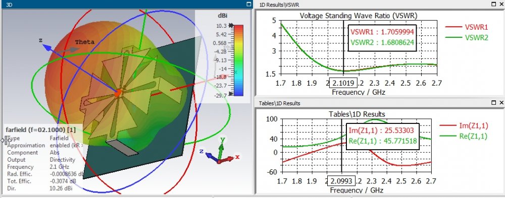
Two ports are well isolated because two orthogonal modes are being exited with this configuration. Bandwidth at S11 -10dB is reduced.
-
Very simple and intersting performance. I guess Circular Pol will work well too by using two of these orthogonal oriented and 90º phase shift. I wonder how to make this much smaller. for the same frequency band.
-
@Ukamurubasu, active S-parameters or F-parameters in CST are useful for phased arrays, or antenna systems in which one would like to quantify the coupling effect between both antennas. This is useful if and only if you use simulataneous excitation. Otherwise there is no sense to look at this active S-parameters. These are measured when the device under test (DUT), such as an antenna, is in an active state, i.e., it is powered and possibly transmitting. In this state, the antenna or network can exhibit different characteristics due to the influence of active elements like amplifiers or transistors. Active S-parameters are crucial for understanding the performance of the device under real-world operating conditions. They can provide insights into parameters like active input and output impedance, gain under active conditions, and the stability of the device when transmitting. This is very important in phased arrays, beamforming. The conventional S-parameters we use to work are called passive S-parameters. You get it!
Added to this, calculate the reactive near field at the corresponding working frequency and check their separation distance on your satellite. So that if they are inside of the near field sphere, avoid it!. Because mutual coupling will be there.
-
On 10/28/2016 at 8:36 PM, Admin said:Construction practice of MIMO antennas Bester...
Very interesting. Thanks for sharing. Learning a lot in this forum.
1 person likes this -
On 17/4/2022 at 9:42 PM, Admin said:,,,it would be nice if you could show through a tutorial how to do an optimization and run faster in CST Microwave Studio...!!!
I agree. Really interesting, BTW
-
On 3/8/2023 at 9:34 AM, Admin said:,,,see that in this topic there is something like that...!!!
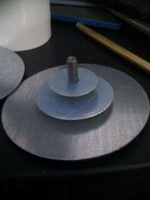
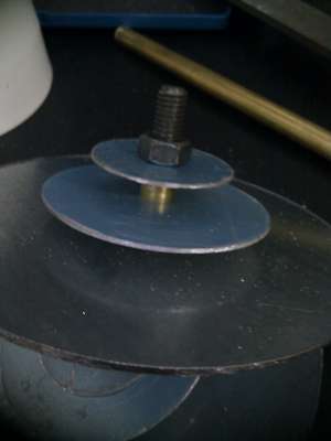
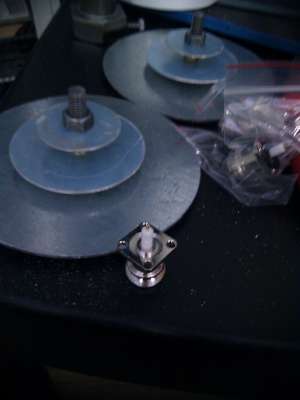
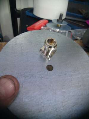
How is the central part? are X-oriented and Y-oriented antennas touching each other?
-
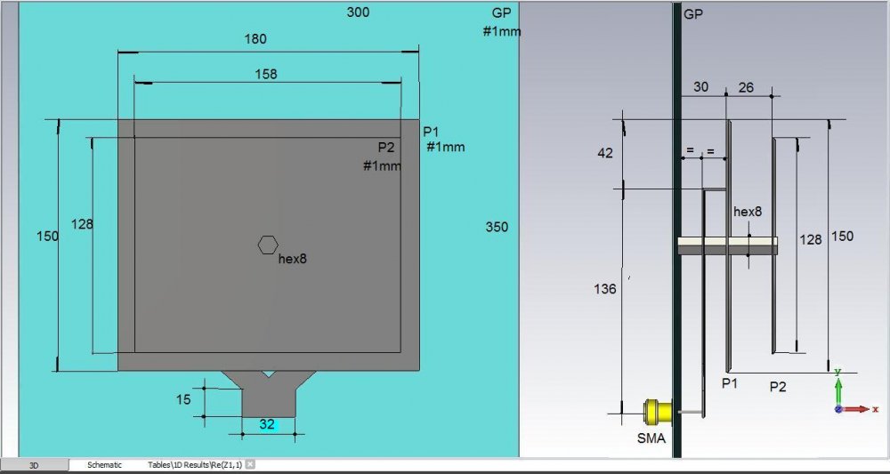
On 5/12/2022 at 5:43 AM, Admin said:Eco, the box is very big and has no point, and the biquad antenna is connected like this...
I see this antenna is connected to the reflector to the other side of the feeding. Why? and what is the difference between connecting it to ground or not at that end position. Thanks
-
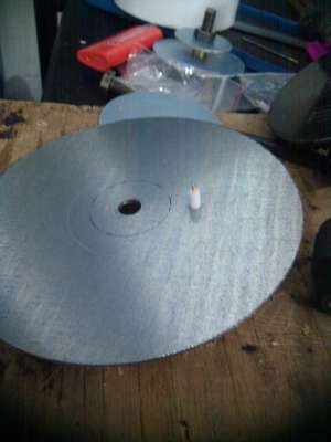
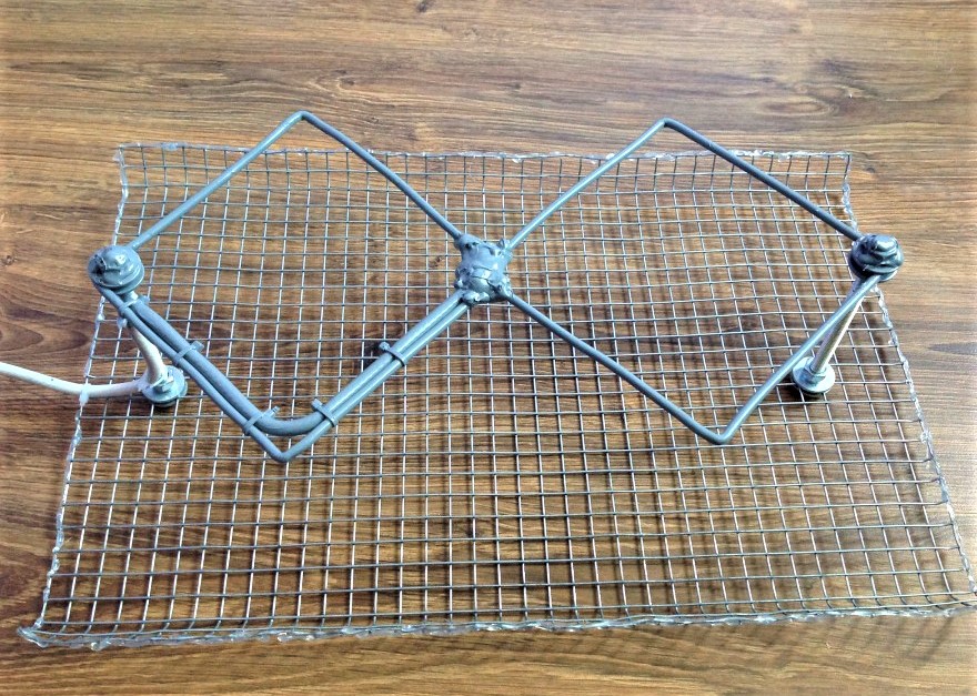
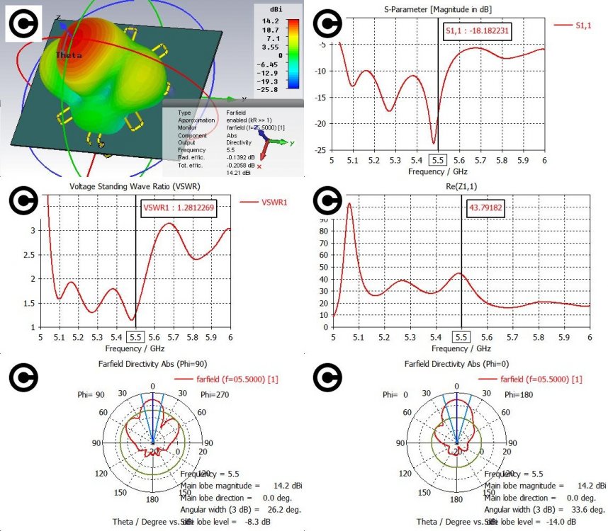
On 3/5/2018 at 9:45 PM, Admin said:The cross antenna is a medium gain and circular polarization structure made of a conductor or a strip line over the ground plane following a cross contour of four or more branches.The construction repeatability is verry easy as well the facility to obtain 14dBi gain in a small antenna.
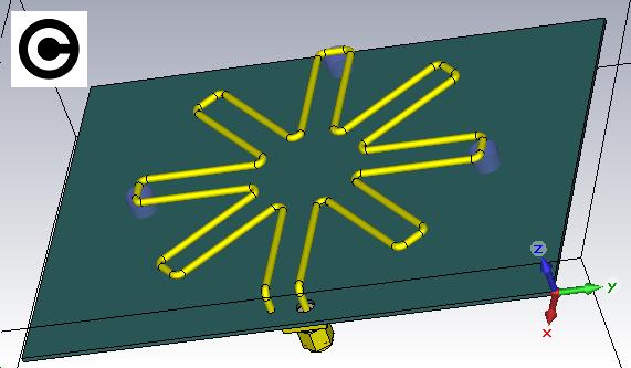
Could you please explain how the wire ends in this design?
Apart, I understand the wire lenght should be lambda/2. Am I right?
Do you have a .cst file to check the design?
Thanks in advance for your help.
-
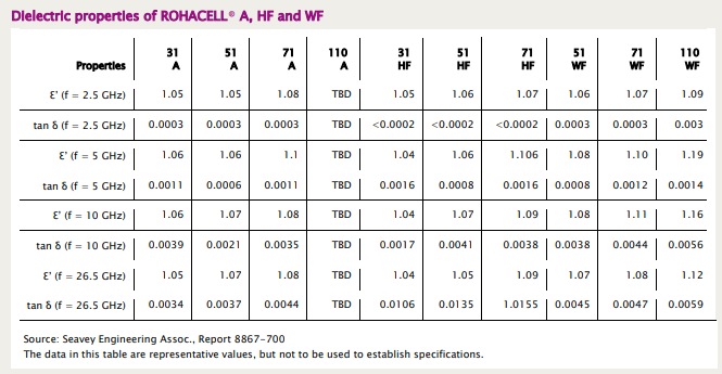
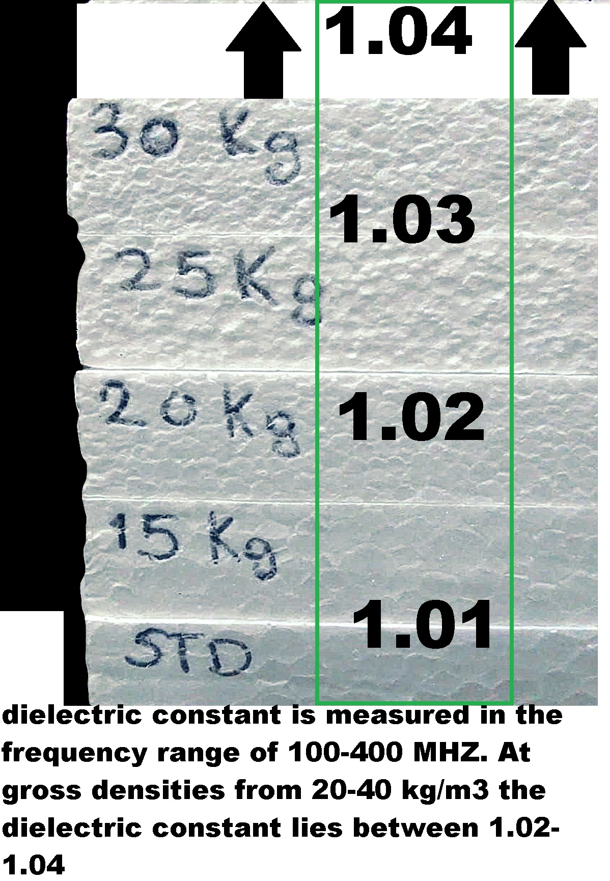
Very interesting, Thanks for sharing! I was working with Rohacell
Since it has very low relative permittivity and low tangent loss too.
 1 person likes this
 -
Very interesting model! Any generic rule for the design? thanks. I mean explanations.
-
On 10/9/2017 at 7:28 AM, Admin said:MrElec see this....
the U-slot variant with truncated corners
Very interesting Could you please share realized gain vs frequency? S11 too? I see you are exciting two orthogonal modes and breaking simetry with truncated corners and U-slot. What is the benefit of this? increase the bandwidth? Improve the axial ratio?
-
On 20/7/2018 at 10:18 PM, Admin said:,,,,something like that...
Hi Guys, Why not one on top each other as gnss antennas. I mean, to make more compact this idea?
-
On 3/11/2023 at 2:06 PM, clanon said:Styrofoam (lowest density better)
cut with resistance wire (nichrome) at 2 mm flat
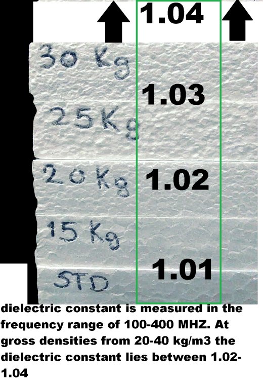
Hi Guys, What is the loss tangent of this material?
-
Sure. I understand that this circuit solves the gain problem. I have never used somehitng like this. Thanks for your suggestion
")
-
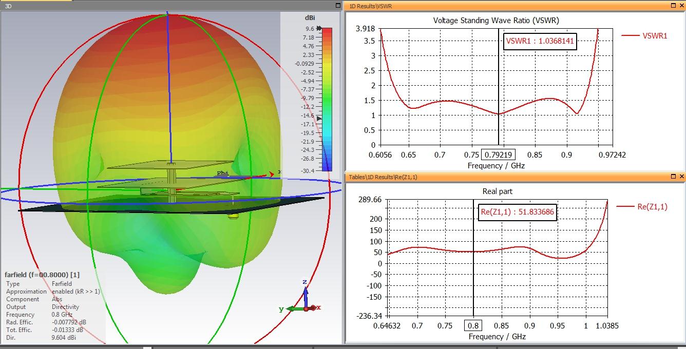
Hello, thanks for your answer @Admin . Apart, to make this antenna work at those frequencies and have 2dBi gain... should this antenna have an amplifier and matching network? I made my own model and the gain is very low. Thanks in advance for your help.
-
Hi guys,
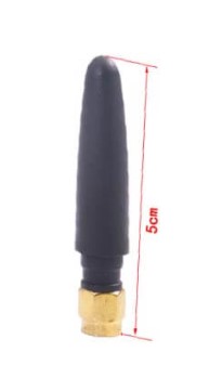
I was impressed when searching online and I saw the 315MHz Rubber Duck Antenna.
How is that possible? What is the shape inside of it? How can an antenna of 5 cm length to have a gain of 2 dBi?
Please check this link: https://ctrfantennasinc.com/small-315-mhz-antenna-low-profile-antenna/
-
11 hours ago, Admin said:,,,,,,only this is possible...
Invalid SAB file, import failed! Thanks anyway.
-
On 6/2/2023 at 8:30 AM, Admin said:,,,for those who want to test...
Hello, could you please share the file as IGES or STEP format, I will then import the neutral file into my 2021 version. 2023 is impossible for me to install it. Thanks in advance
-
Hi Dr.Pepper, have you developed the data base?
Let me know and I will contribute. Although we can share in this forum too. In a near future I will. I like it. The help in this forum is really good and deserves it.
-
No, you are right
haha
I am interested on these type of antennas. In fact, I want to use this antenna solution to cover 30-170 MHz, with gain higher than -25 dBi. And consider a weight to be less than 1 Kg. A very challenging antenna. But who knows... perhaps, including ferrite and some dielectric materials I can achieve it. Otherwise... I will try another technology. Thanks for your support and asking.
-
On 2/2/2023 at 11:33 AM, tomasbj said:Hello, could you please help me with finding the matching between the design I made and the paper. I can not find the same results. See attached file. cst2021 Thank you
It seems I forgot to upload the paper X
1 person likes this -
On 6/2/2023 at 2:30 AM, Admin said:,,,for those who want to test...
Great! Thanks. I am not able to check/test it until some days after, but when I can I will tell you how it looks
")
-
On 2/4/2023 at 9:21 AM, Admin said:,,,this system is a bit complicated, but I think it can be executed...!!!
,,,and why the frequency of 300MHz...???,,,model of a tunable antenna embodiment with Variable capacitors....!!!
I don't understand your question when you said, why at 300 MHz. Do you mean why is this antenna working at 300 MHz? Physically talking.
Or why am I interested on this frequency range?


in Antennas for 2.4 GHz band
Posted
Awesome collection. Good job.