Register now to gain access to all of our features. Once registered and logged in, you will be able to contribute to this site by submitting your own content or replying to existing content. You'll be able to customize your profile, receive reputation points as a reward for submitting content, while also communicating with other members via your own private inbox, plus much more! This message will be removed once you have signed in.


Admin
Administrators-
Content count
4451 -
Joined
-
Last visited
Posts posted by Admin
-
-
 2 people like this
 -
some data...
-
 1 person likes this
 -
-
Congratulations ... very good work Andrew77....!!!!!!!!!!!!!
it must to have made adapting impedance...!!
-
Excuse me, but I don"t understand what you want to post here .. !!
Can you refer to something like this...!!!

,,,or like this...
 1 person likes this
 -
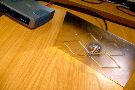
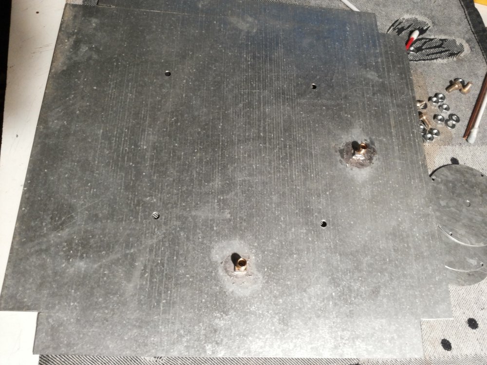
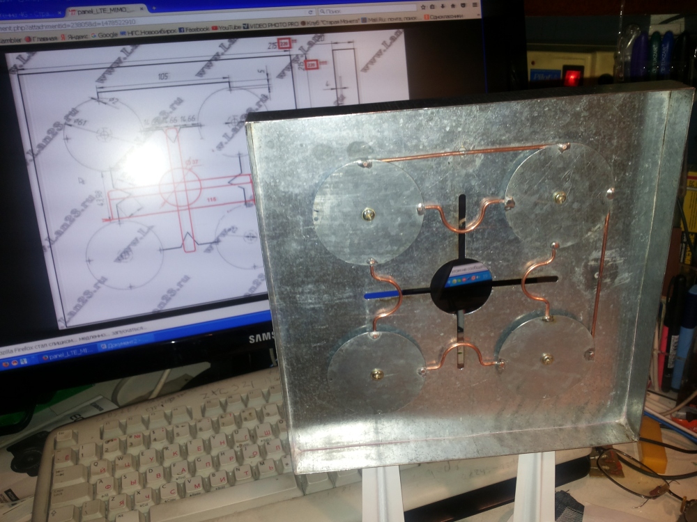
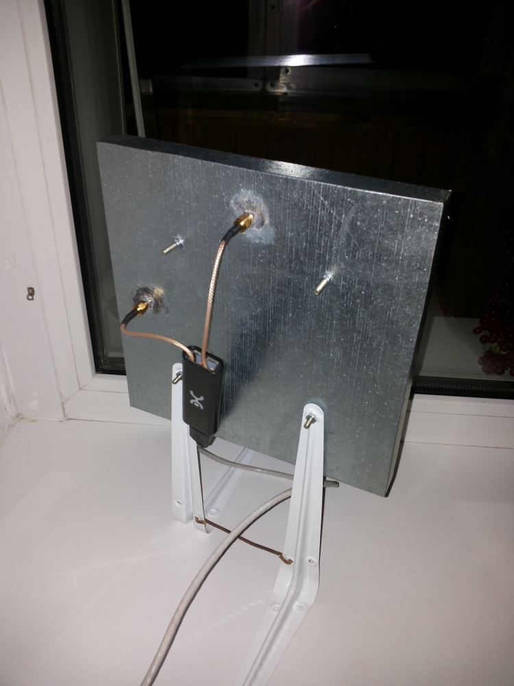
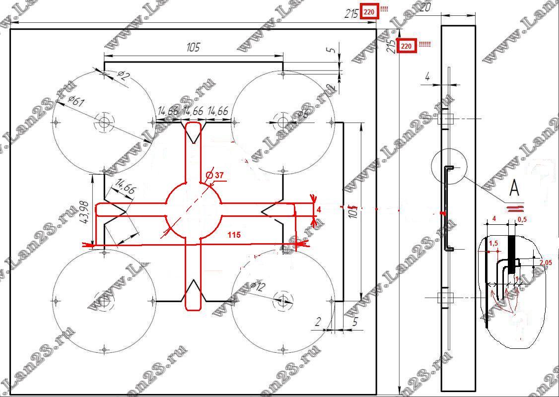
Galvanized sheet 0,3-0,4mm
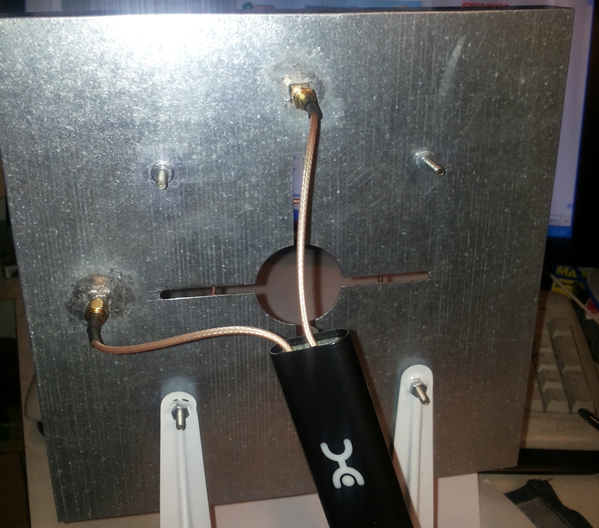
Another kind of power supply via coaxial cableVersion of REMO.
 1 person likes this
 -
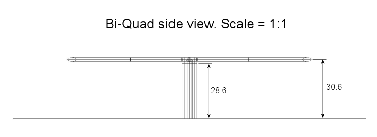
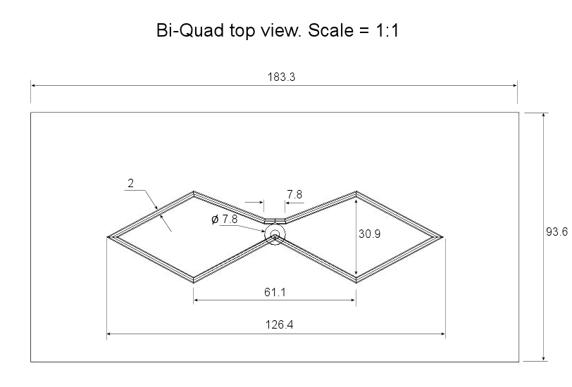
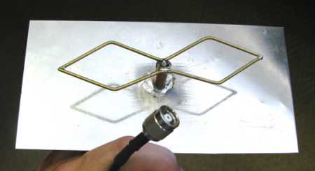
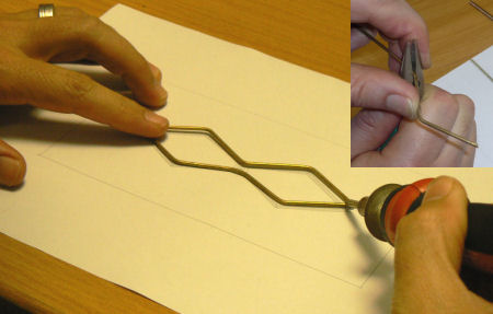
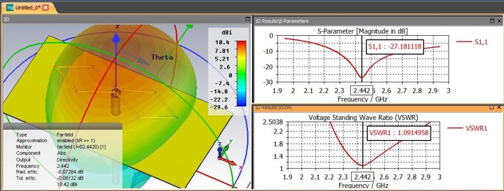
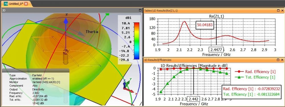
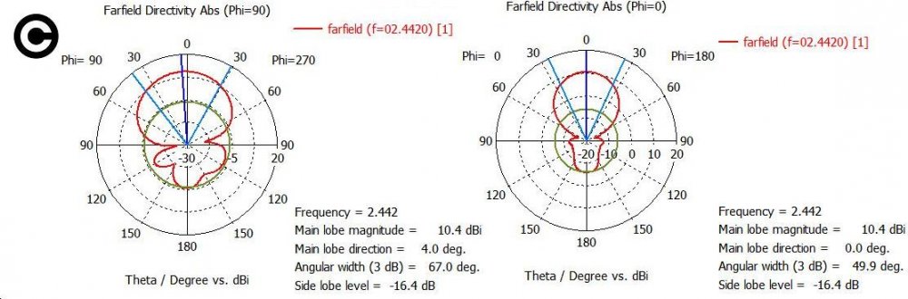
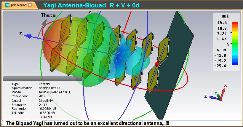
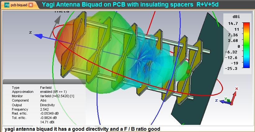
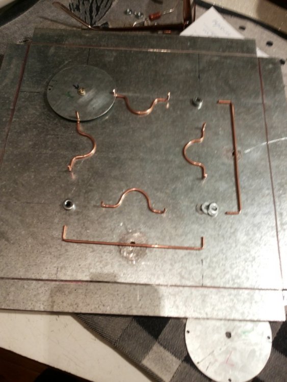
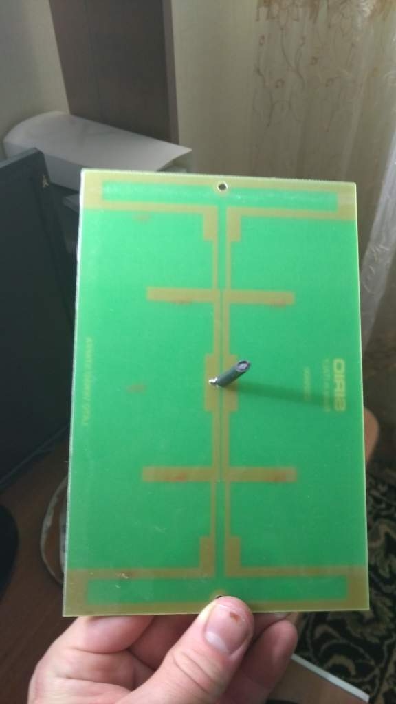
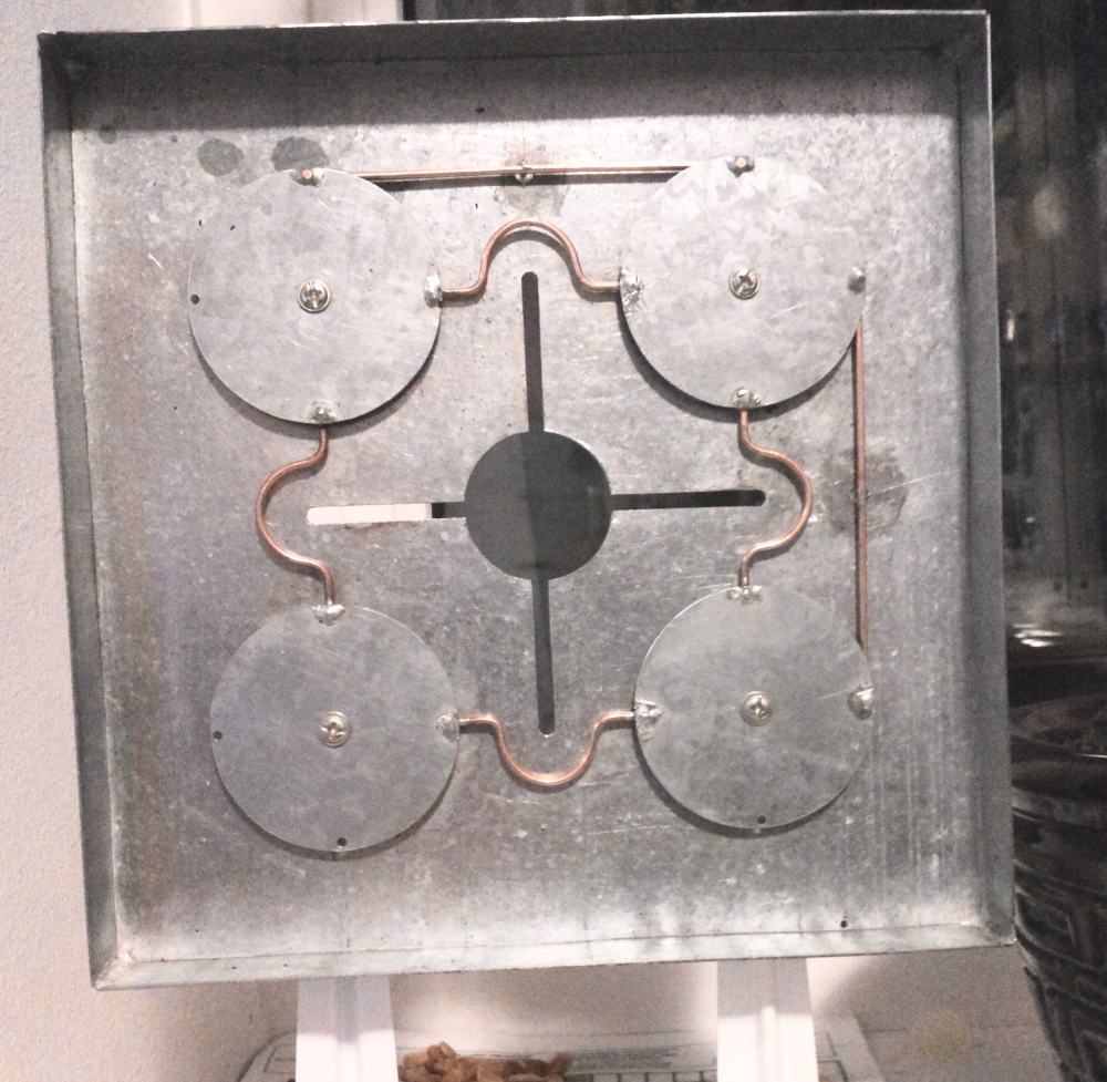
Biquad Construction

 4 people like this
 -
To take full advantage of MIMO (currently used in 4G LTE communications) two antennas must be used. When installing directional antennas like a panel antenna, the first antenna must be rotated horisontally to a 45 degree angle and the second to a 135 degree angle. This is because of "polarisation diversity". LTE uses polarisation diversity to help distinguish between the two data streams sent from the tower.
This MIMO panel antenna for 3G has the advantage of good isolation between the two ports.
 2 people like this
 -
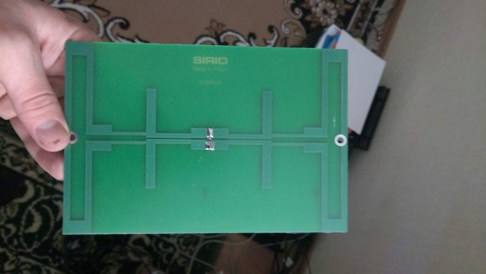
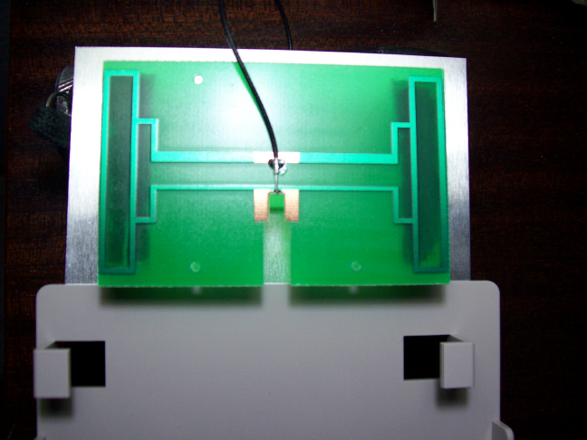
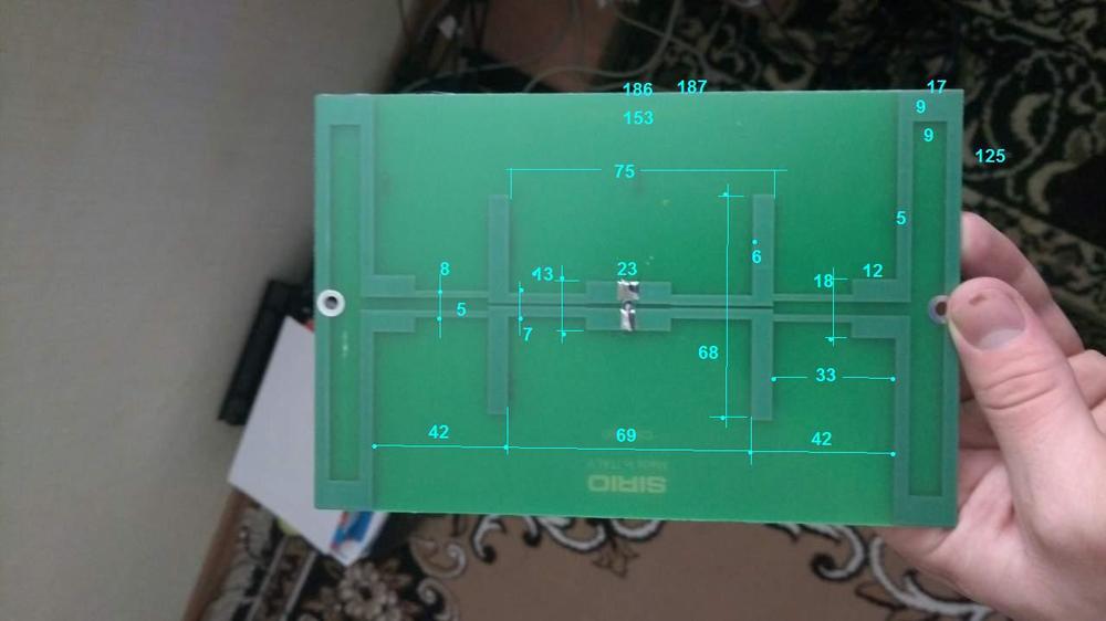
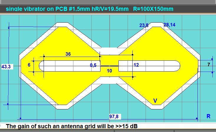
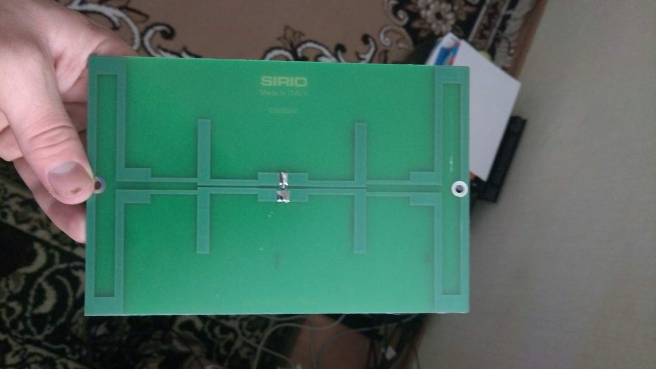
The radiant element is made on PCB

this antenna is better than this...
 1 person likes this
 -
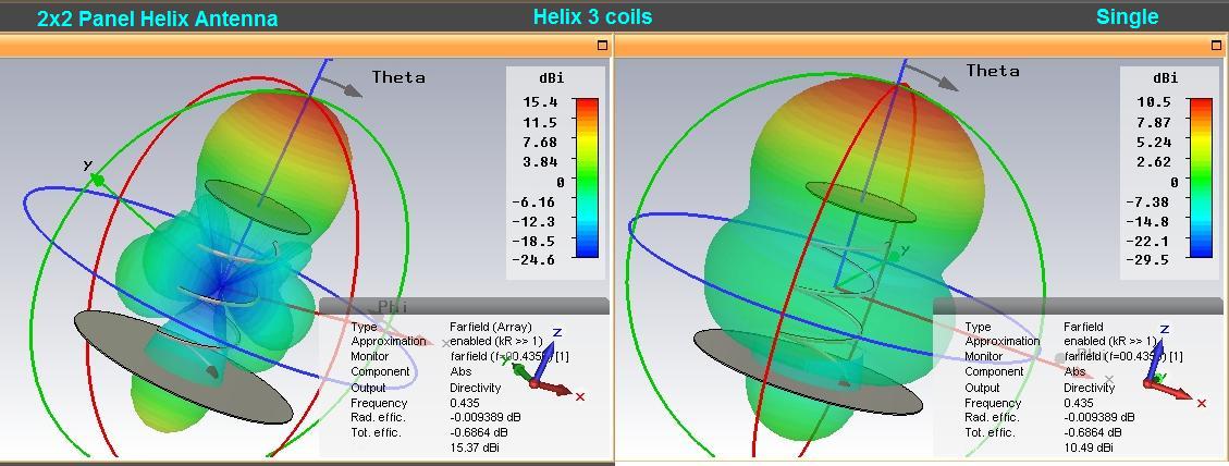
2 hours ago, Andrew77 said:Can this disk be applied to longer helical antennas (2 wavelength) and @ lower frequency? (EG 430 MHz)??
thanks
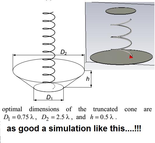
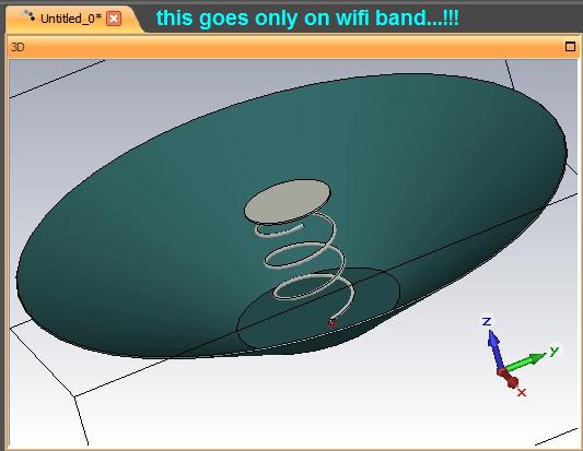
Yes, this parasitic disc can be applied but only at helical antenna with 3...5 coils or at least reduced by 70-71%.!
-
 1 person likes this
 -
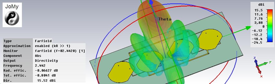
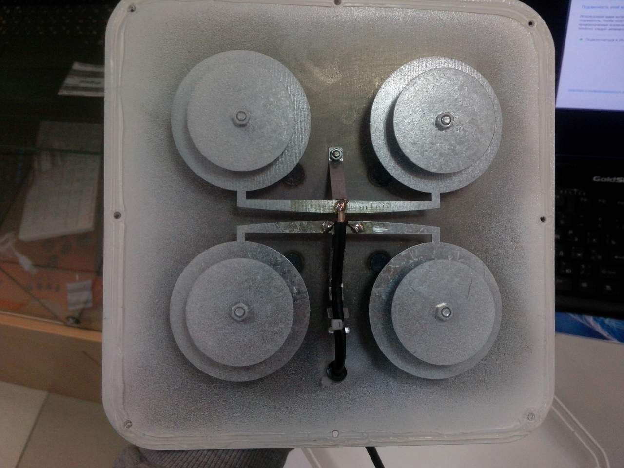
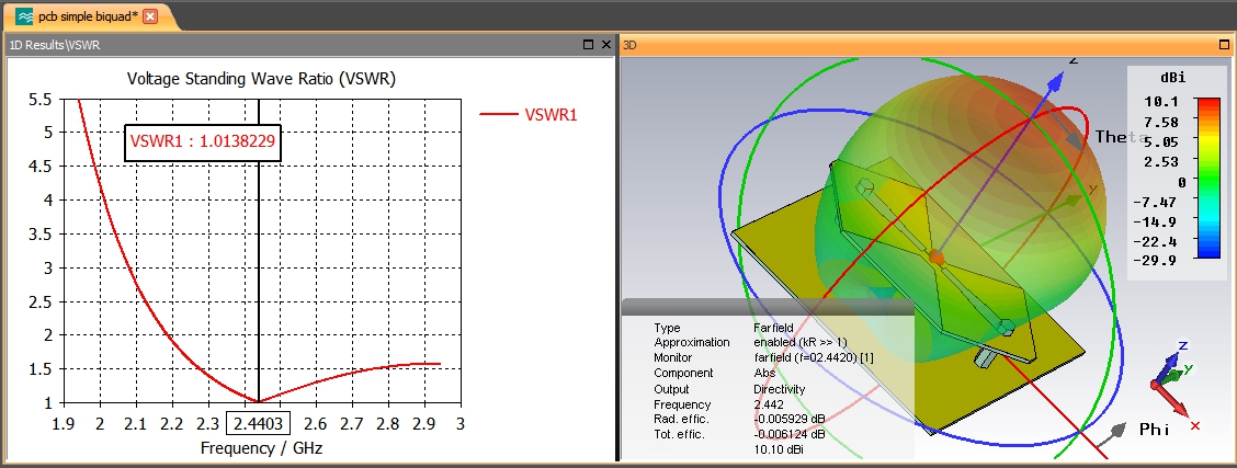
,,,a biquad antenna on PCB(10,5dBi) and panel antenna with 4biquad(16.5dBi)...
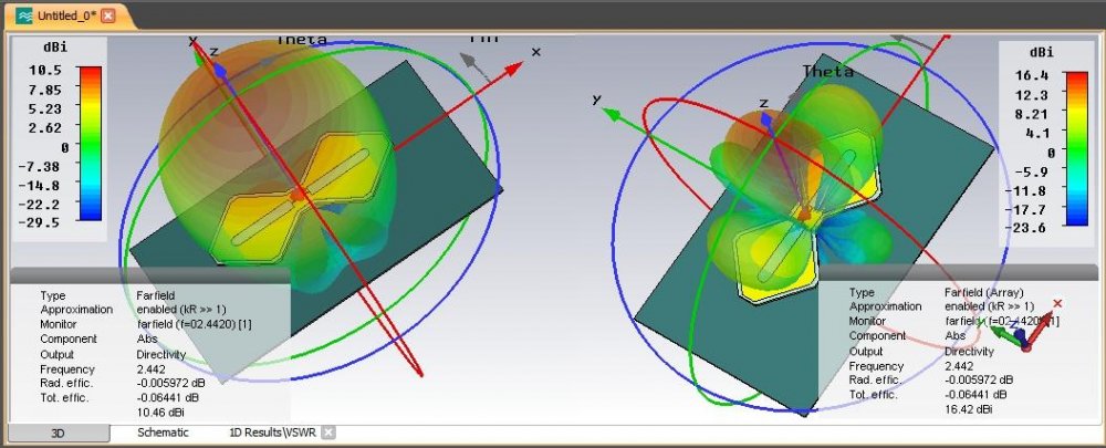
The Best ....!!!

 2 people like this
 -
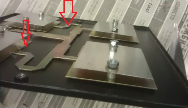
,,,by Oveco ...
When used with the WiFi adapter Alfa AWUS036H managed to keep the relationship at a distance of more than 10 nautical miles (18.5 km).
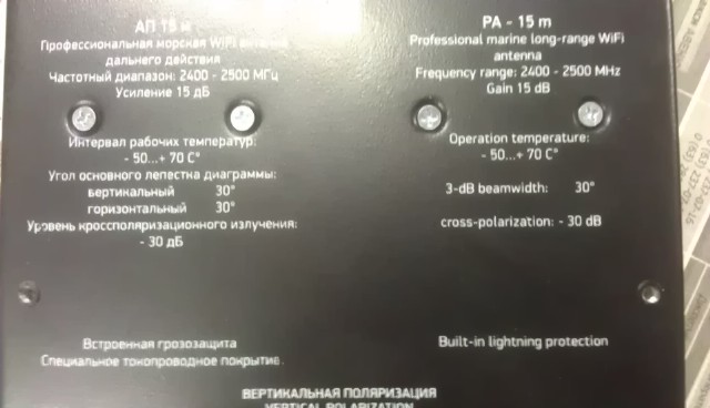
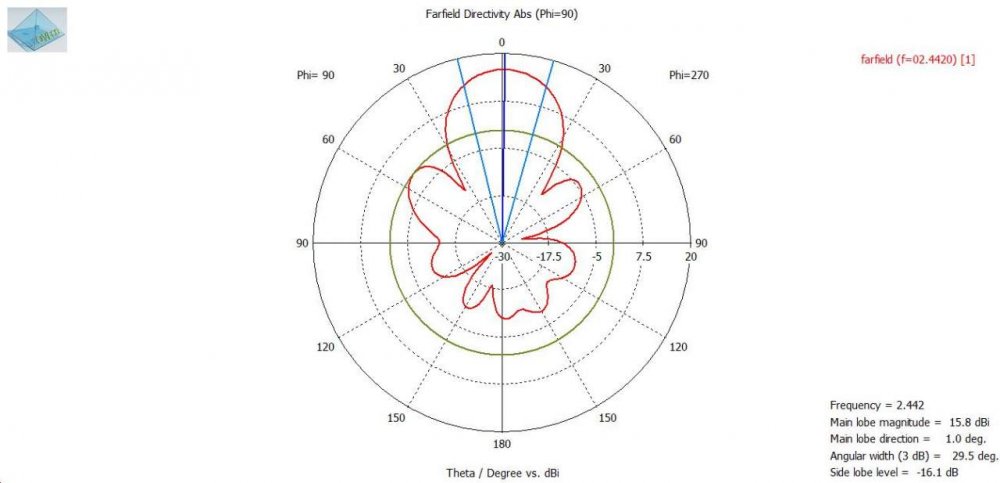
Features Wi-Fi antennas AP-15m:
* Operating frequency band: 2.4 GHz
* Gain: 15 dB
* Angle of the main lobe: 30\30 degrees
* Weight: 0.75 kg
* Dimensions (without mount): 20х20х2см
* Crosspolarization: -30dB
* Antenna efficiency: more than 90%
* 2m cable included, SMA connector
* The antenna has a swivel mount on the tube with the wing nuts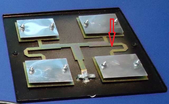
 2 people like this
 -
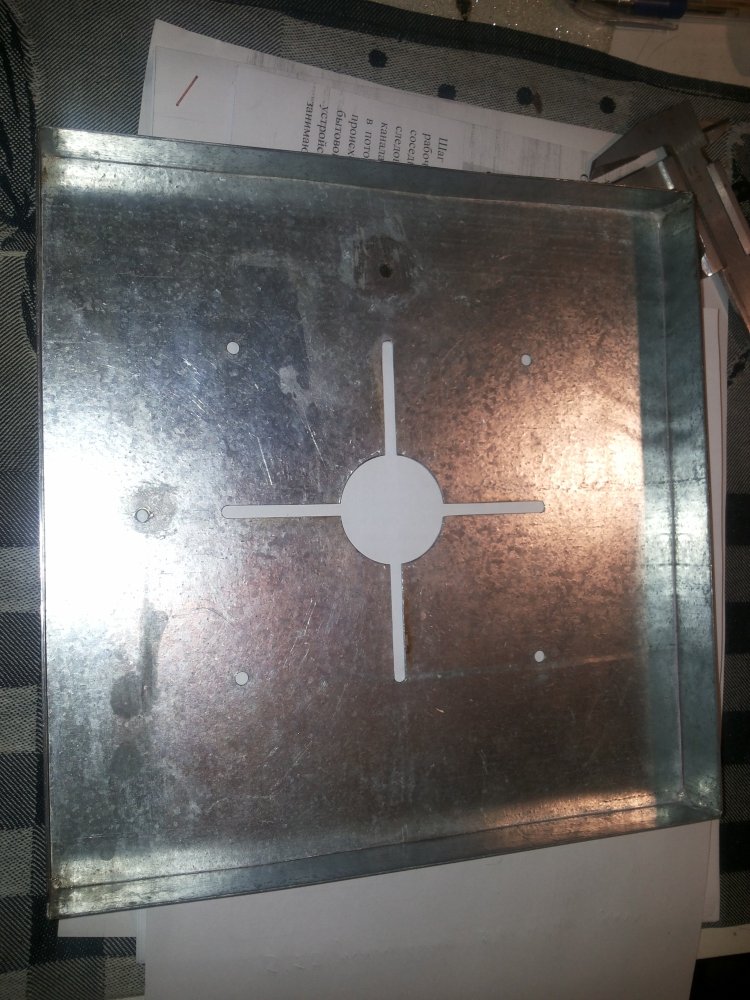
a practice of execution by Starik0...


 3 people like this
 -
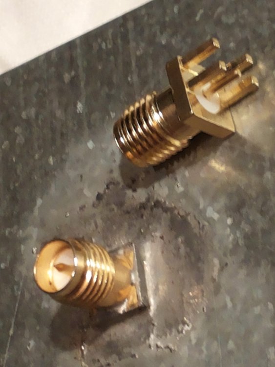
Another variant of the plug.
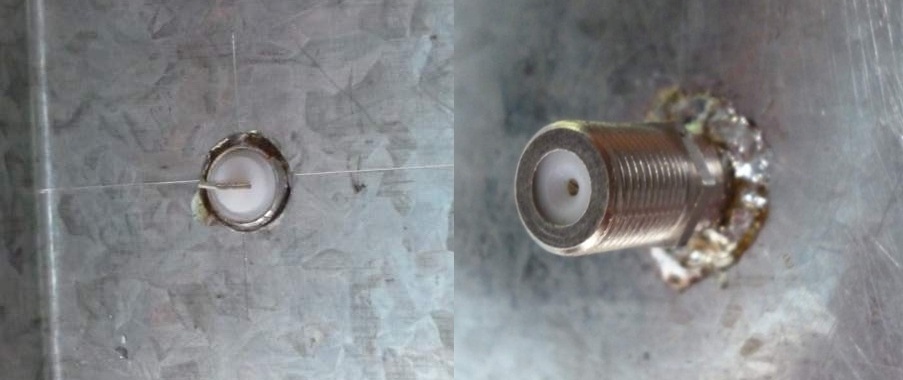
-
Can be made of a pcb board and a metal reflector

 1 person likes this
 -
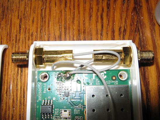
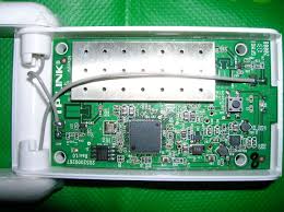
Chipset Atheros AR9271
The interesting device is "full N 300 Mbps" how it is full I Hate, 2R2T . But the fact that he uses on the reception of both antennas it is a fact, try to put on the first antenna panel 18Dbi result is worse than with two pins.
Very good sensitivity , compared with a whistle at the base of Ralink - no worse.
Fully compatible with Commview.
In BackTrack5 and WifiSlax driver are - app.
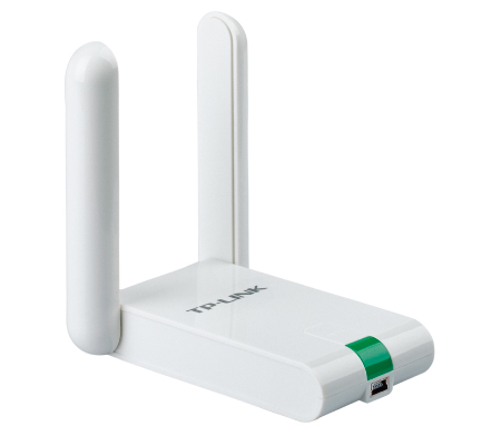
From slightly altered device: standard broke off the antenna ,put the connectors and soldered the cable to the antennas.TP-link WN822N
TP-link WN822ND
![20130330_165746[1].jpg](https://www.wifi-antennas.com/uploads/monthly_2017_01/58778f967e7ae_20130330_1657461.thumb.jpg.af80cbe4c941e8ec7f8767f2c5c856cf.jpg)
TP-link WN822N
-
,,,for Guest...
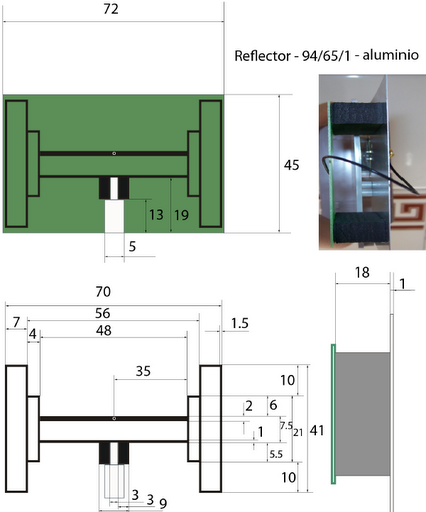
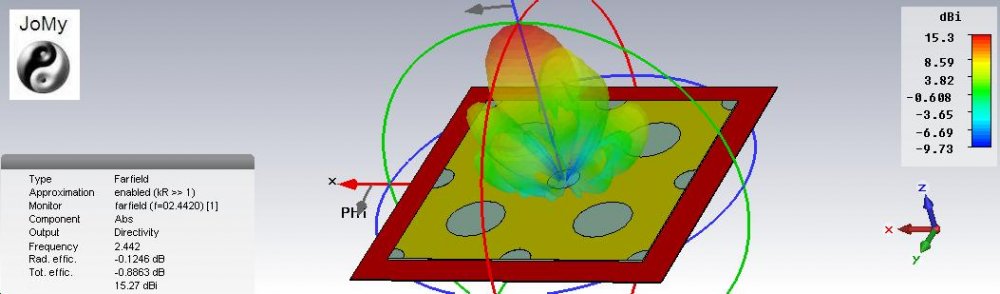
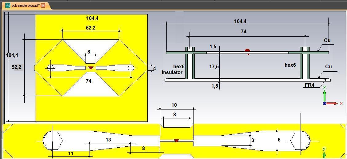
dimensions gauge reflector
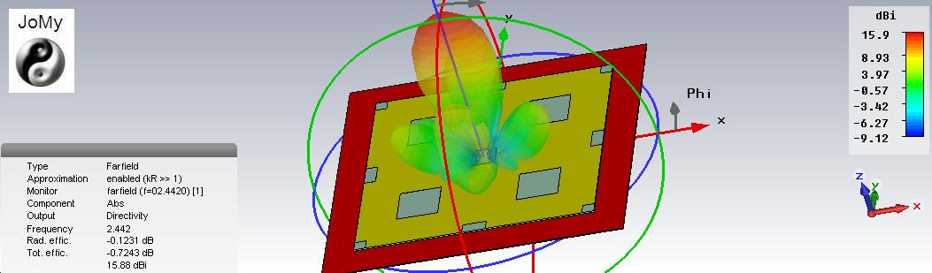
With such dimensions of the reflector it is possible to be such an antenna gain
-
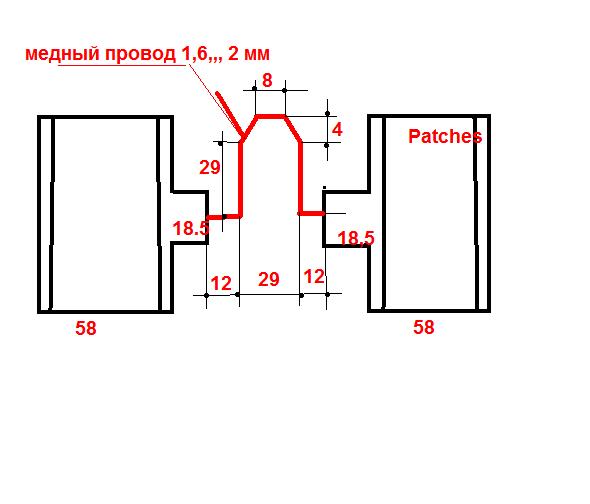
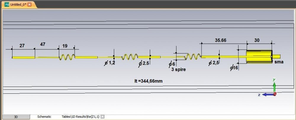
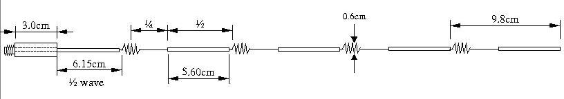
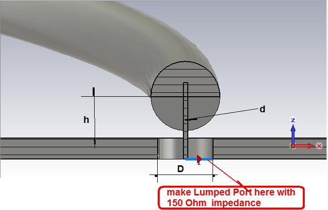
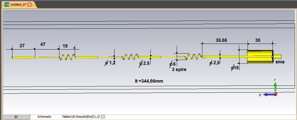
Adaptation line dimensions
 1 person likes this
 -
and with the lateral wing version...
 1 person likes this
 -
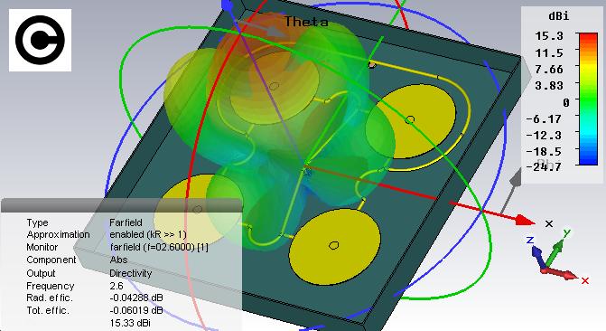
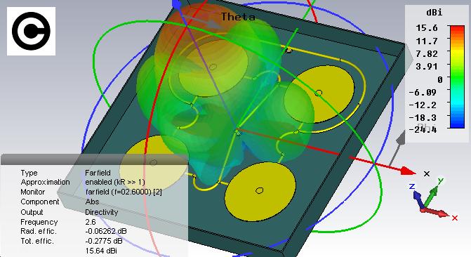
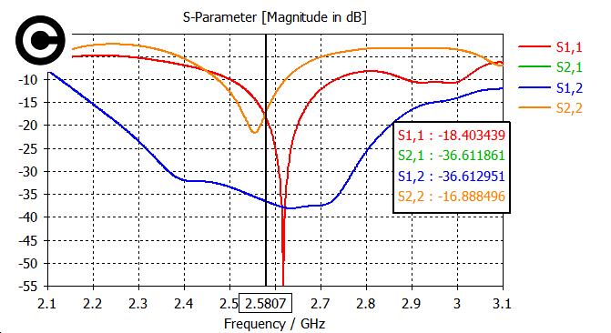
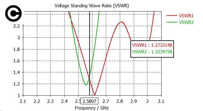
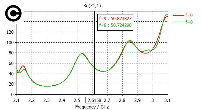
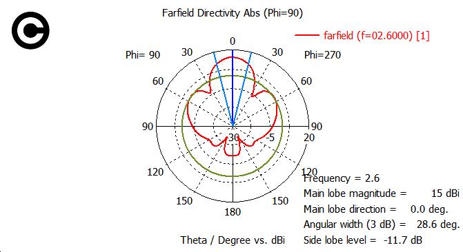
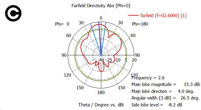
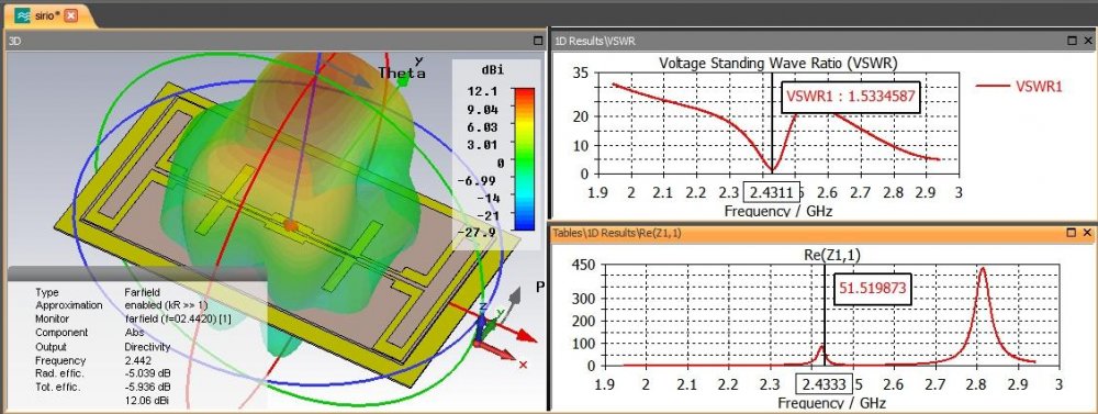
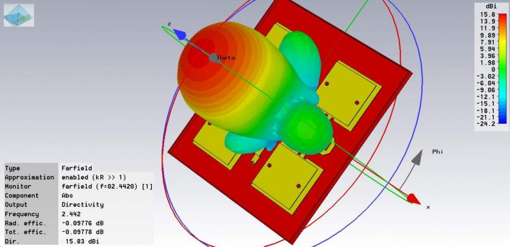
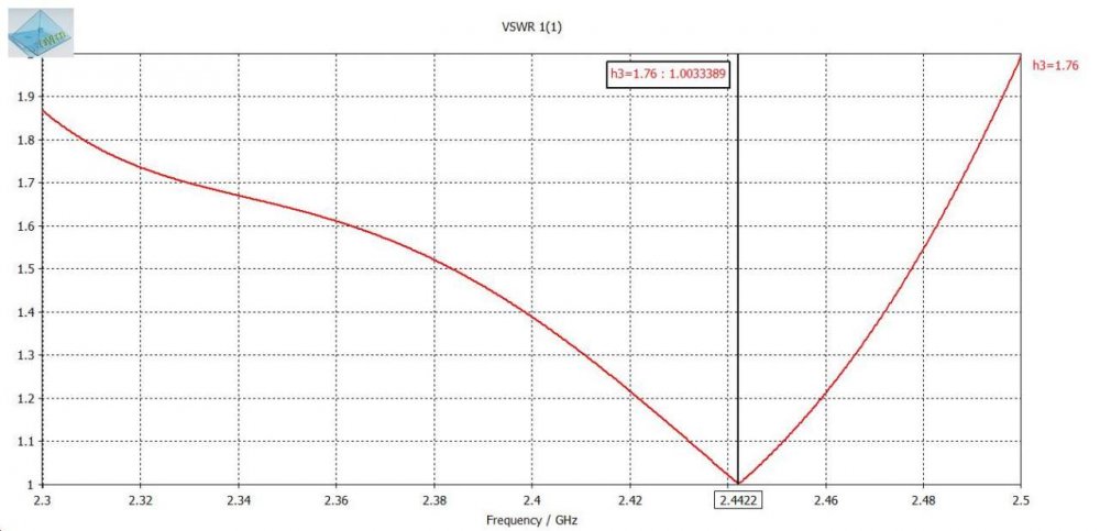
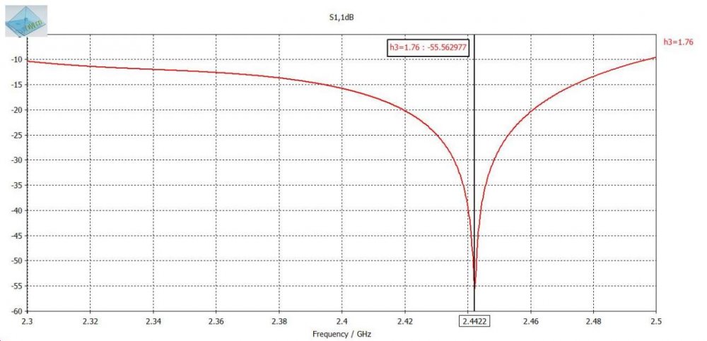
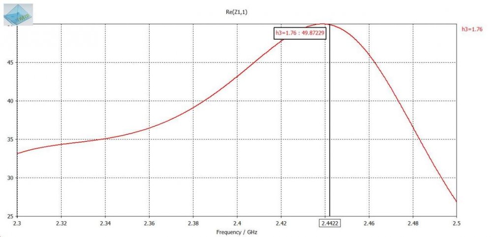
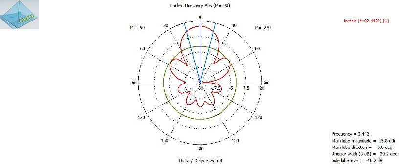
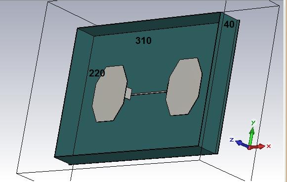
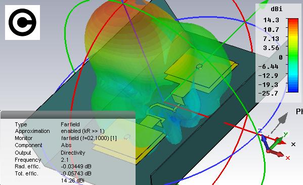
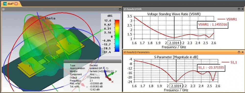
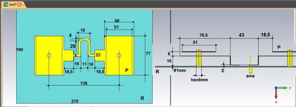
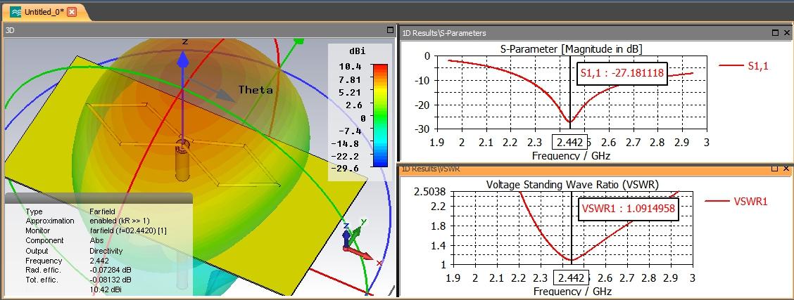
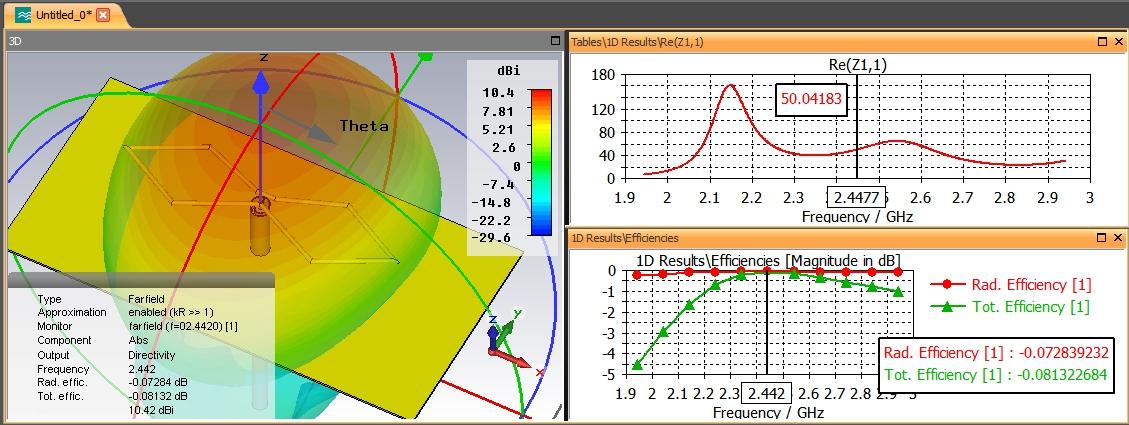
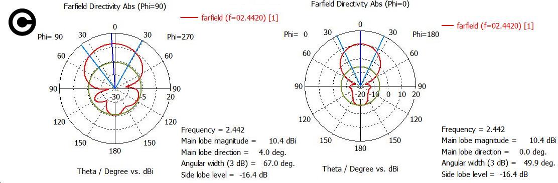
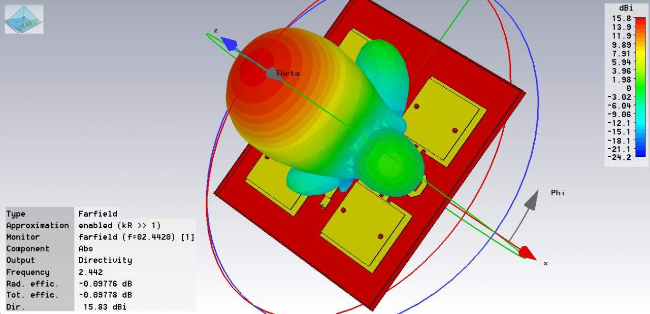
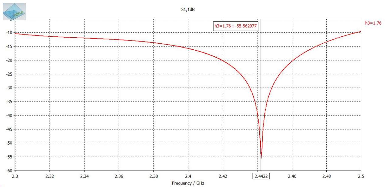
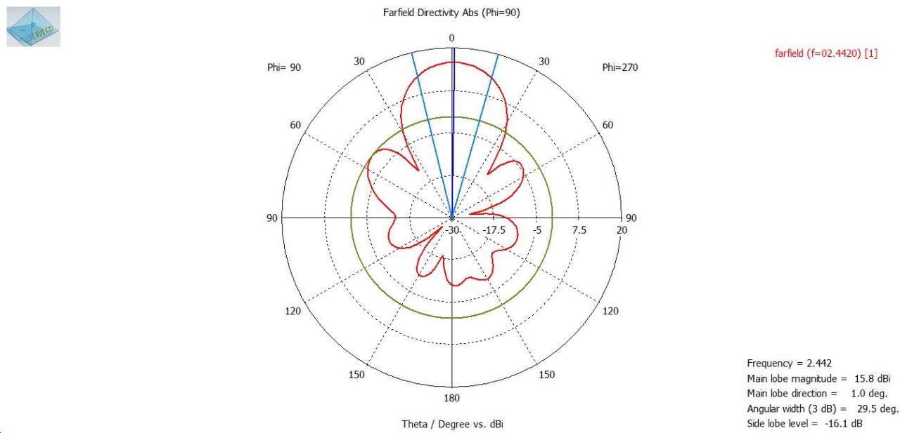
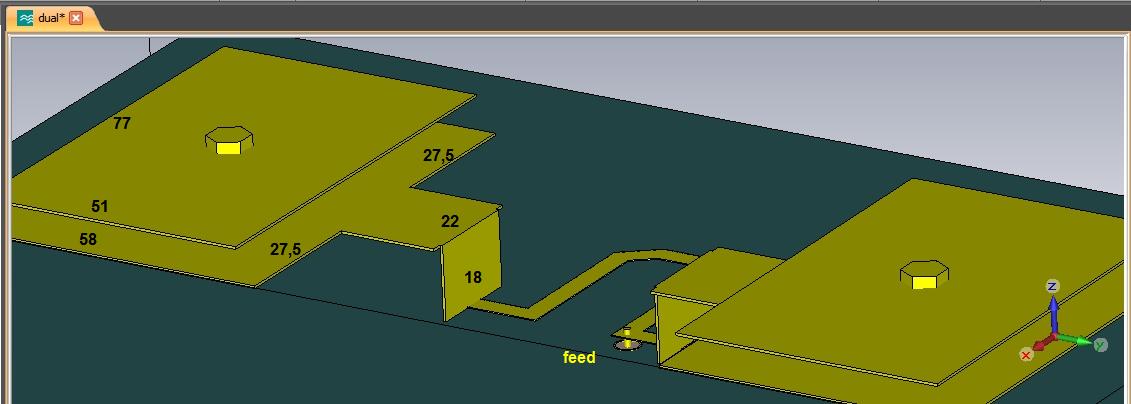
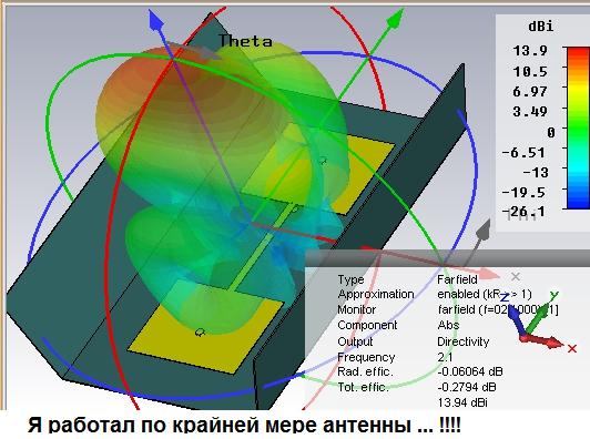
A new UWB panel antenna with 2 patches and 2 rectangular directors for the 2.1-2,55GHz frequency

 1 person likes this
 -
-
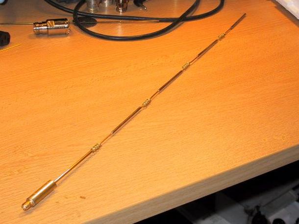
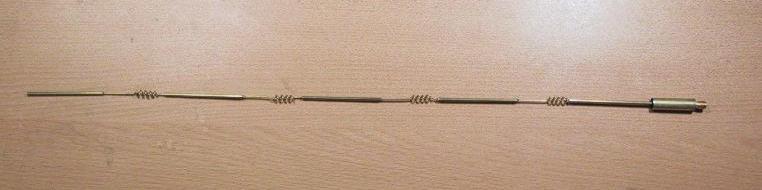
In telecommunications, a collinear antenna array is an array of dipole antennas mounted in such a manner that the corresponding elements of each antenna are parallel and collinear, that is they are located along a common line or axis.
Collinear arrays of dipoles are high gain omnidirectional antennas. A dipole has an omnidirectional radiation pattern when in free space and not influenced by any other conductors in that it radiates equal radio power in all azimuthal directions perpendicular to the antenna, with the signal strength dropping to zero on the antenna axis. The purpose of stacking multiple dipoles in a vertical collinear array is to increase the power radiated in horizontal directions and reduce the power radiated into the sky or down toward the earth, where it is wasted. They radiate vertically polarized radio waves. Theoretically, when stacking idealised lossless dipole antennas in such a fashion, doubling their number will produce double the gain, with an increase of 3.01 dB. In practice, the gain realized will be below this due to imperfect radiation spread and losses.


![20130330_165746[1].jpg](https://www.wifi-antennas.com/uploads/monthly_2017_01/58778f9648aff_20130330_1657461.jpg.58e0218f6a051b7258c114754710c40e.jpg)

in HF, VHF and UHF
Posted