Register now to gain access to all of our features. Once registered and logged in, you will be able to contribute to this site by submitting your own content or replying to existing content. You'll be able to customize your profile, receive reputation points as a reward for submitting content, while also communicating with other members via your own private inbox, plus much more! This message will be removed once you have signed in.

clanon
Members-
Content count
817 -
Joined
-
Last visited
Posts posted by clanon
-
-
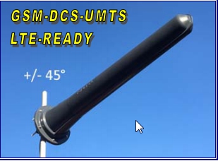
couldn't find it (was on a catalog) this is similar https://www.protel-antennas.com/files/22-Amplified-portable-antenna-ARK103XZ-PROTEL-HANDHELD-INTERFERENCE-FINDER-GSM-LTE-DCS-UMTS-data-sheet.pdf
1 person likes this -
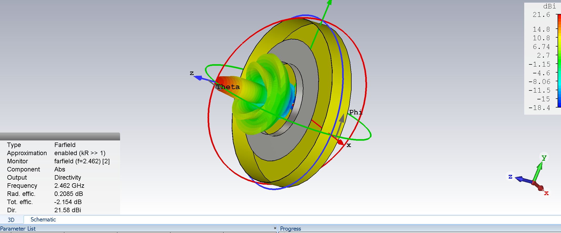
@eco32 you NEED to try CST...is very intuitive and fast...and better results...
backfiring CIRCULAR PATCH should have better shape...LOBE
1 person likes this -
add a rim and ring...
 2 people like this
 -
6 hours ago, eco32 said:What about dieletric as a microwave lens? It's probably the only chance to get more than 17dBi.
PES (Styrofoam) low density...1.075-1.1 Dielectric Constant (almost NO LOSSES)
-
-
On 29/1/2025 at 8:36 PM, Harry36 said:This is all well and good, but what does this have to do with me? Did I say that's not true? The option that was originally posted by the Admin in the topic is not a circularly polarized antenna. Without phase-shifting elements in this design it is impossible to obtain circular polarization. This is clear to me. in the initial version it is a regular mimo dipole. Perhaps the admin used a phase shift on the port when modeling. I have nothing to do with this.
i wasn't blaming anyone , just asking for YOUR opinion...

-
-
56 minutes ago, Harry36 said:???
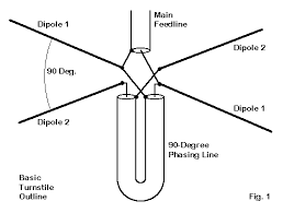
without 90 degrees phase shift (at half wave center Feed)...two crossed dipoles are NOT Circular Polarized...
-
11 hours ago, papagayor said:Thank you very much for your time and your suggestion. Thinking for something "compact size" for feeding a satellite disk as reflector. Also I'm looking at the following post and thinking about making something similar as the attached file. Could you .....please..... check it??????
-
without the delay is only two dipoles one Vertical the other Horizontal (Crossfeeding High Isolation BAD) @Harry36
-
Circular pol means : there is 90 degrees delay between feeding points...to force a rotating 1/4 rotation on Each quarter wave (half dipole)...imho built in the reflector (strips)
 1 person likes this
 -
Looks like each one receives a different pol- at different timing...
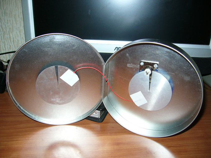 Anti-phase it seems
LHCP and RHCP...
1 person likes this -
On 19/11/2023 at 6:12 PM, tomasbj said:Hi Guys, Why not one on top each other as gnss antennas. I mean, to make more compact this idea?
Each one has a 90 degrees orthogonal difference . Polarization is the same but Phase is 90 degrees off ...
-
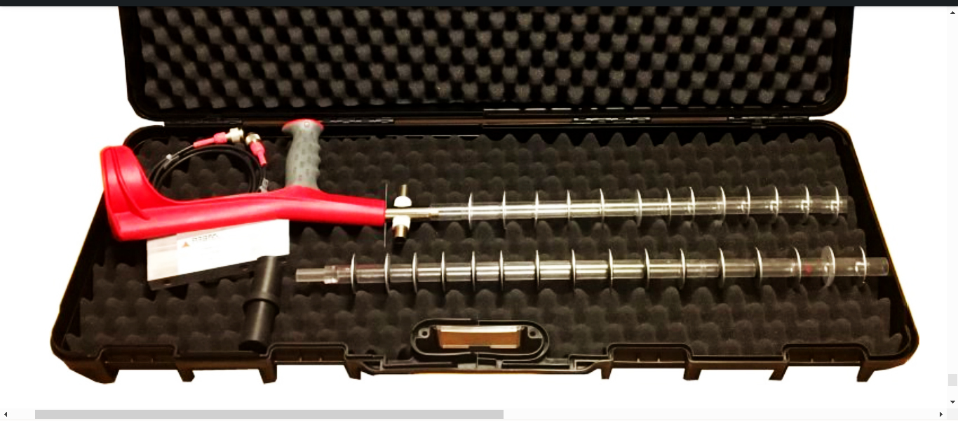
On 10/1/2025 at 2:27 PM, Admin said:,,,okay, and inside it has disc elements...???
probably for high band...(only directors)
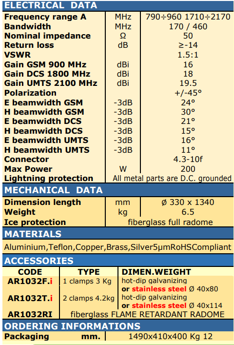
lower band MUST BE Tubes both crossed and combined on one output is 33 cm by 1,34 meters
 1 person likes this
 -
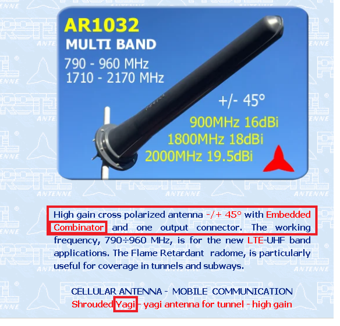
On 10/18/2020 at 9:32 PM, Admin said:790÷960 MHz ang 1710÷2170 MHz... this is completely different .... !!!
,,,show me, what it's like inside...????

 1 person likes this
 -
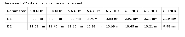
FR4 EATS 5ghz energy
PES and copper tape would be MORE EFFICIENT .
ALL METAL even better
 1 person likes this
 -
7 minutes ago, naumoves said:My design is based on Maarten Baert's recommendations. fr4 1.mm (loss free) and 0.035mm copper (loss free)...
coax specs might be off
 1 person likes this
 -
3 hours ago, dumser2 said:Triple Feed Patch antenna
https://www.maartenbaert.be/quadcopters/antennas/triple-feed-patch-antenna/
could you post a .stl (cst2019 here)
-
different solver and different settings would give different F resonance . BUT dielectrics play the BIGGEST ROLE...try higher dielectric constant WHAT THICKNESSES ? METAL moves fr UP
ussually is 0.035 mm copper 1.53mm FR4
1 person likes this -
Only way I see to increase gain...is a reflector (Not omni anymore , but could add 3dbi) (multiplying elements cuts down on bandwidth and impedance changes)
-
the slits slots must be for wideband impedance matching...for FR4...
.mp4_snapshot_00.00.000.thumb.jpg.189245e3009e87cc14e127b64be5d00e.jpg)
.mp4_snapshot_02.17.117.thumb.jpg.7e2bbc036258456cf75f3109b1c714bb.jpg)
.mp4_snapshot_02.02.117.thumb.jpg.5ed369ef6a20b416244594a22ffcaac1.jpg)
.mp4_snapshot_01.52.117.thumb.jpg.3c10ede702415aab0a99a24977d55440.jpg)
-
THIS dual band could be easier...FR4 moderate gain is for 2.4 and 5.2 but could be TWEAKED i think...
 1 person likes this
 -
USE POLYSTYRENE FOAM (STYROFOAM) Low density as a spacer ,is TRANSPARENT to RF and have NO LOSSES
1 person likes this -
On 10/31/2024 at 7:24 PM, dumser2 said:I seem to be doing something wrong. Can you still reset the cst file?


PORT ISN'T THERE , dangling (not touching metal on BOTH SIDES) or wrong port...CHECK WARNINGS
.jpg.d0d9cb5184ff75cd0bb20ef990ea0f62.jpg)
.mp4_snapshot_00.00.000.jpg.eb820773112c83aa41cb87069b98f1d3.jpg)
.mp4_snapshot_02.17.117.jpg.4d2a6ed90769d7d673b3284732aa924c.jpg)
.mp4_snapshot_02.02.117.jpg.7a90e58dbcb71aeed67d1f57deeed5b2.jpg)
.mp4_snapshot_01.52.117.jpg.140cb96f6a88ea6e753d5116753d89d0.jpg)


in Antennas for mobile communications
Posted · Edited by clanon
Integrated LNA amp for Interference finding...All PET PC Boom tube...?
Catalogo-Antenne-di-Misura-e-Monitoraggio-Monitoring-Protel-023.pdf