Register now to gain access to all of our features. Once registered and logged in, you will be able to contribute to this site by submitting your own content or replying to existing content. You'll be able to customize your profile, receive reputation points as a reward for submitting content, while also communicating with other members via your own private inbox, plus much more! This message will be removed once you have signed in.


Admin
Administrators-
Content count
4877 -
Joined
-
Last visited
Posts posted by Admin
-
-
 1 person likes this
 -
-
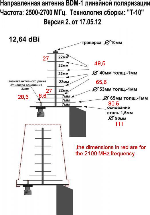
,,,,all are 10mm..!!!
-
120x180 mm-reflector...distance=90mm
-
I no longer have this file...!!!
-
I think it's possible, try it...!!!
-
2 minutes ago, DavidER said:Will a 6-8mm stud with nuts work?
,,,,maybe, but simulations need to be done...!!!
-
Anyway, these dimensions I gave you must be verified by simulation.
 2 people like this
 -
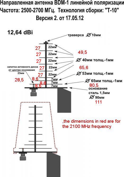
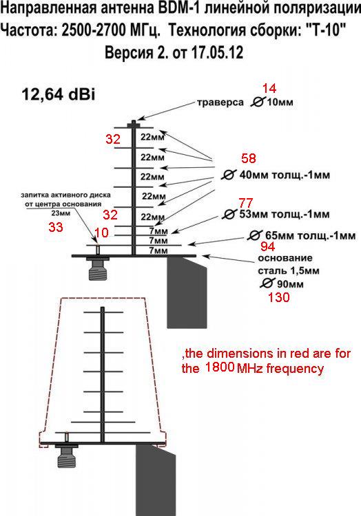
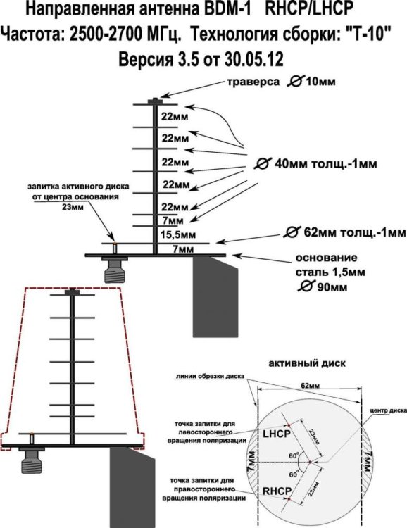
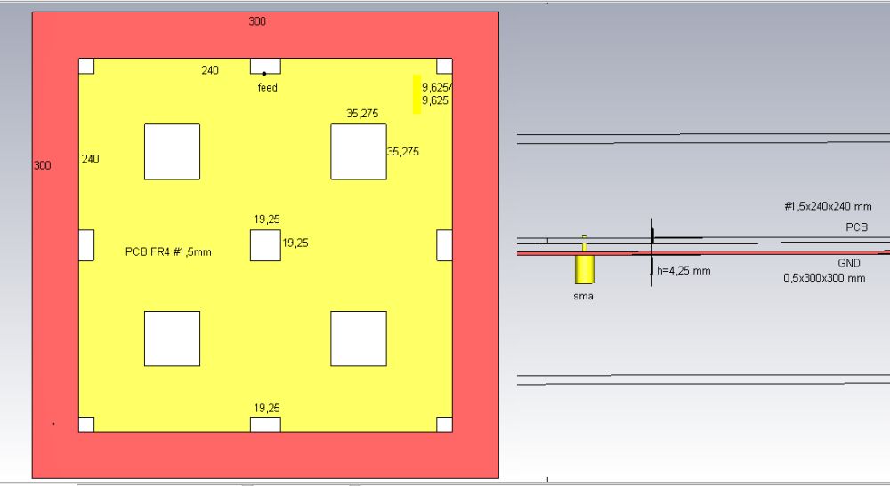
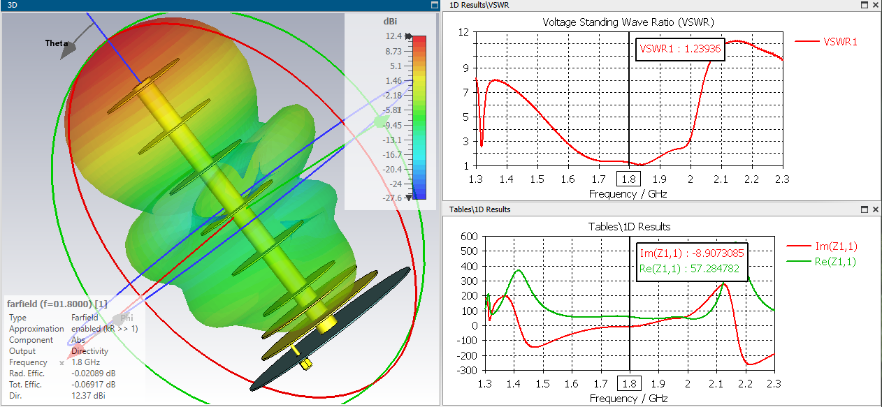
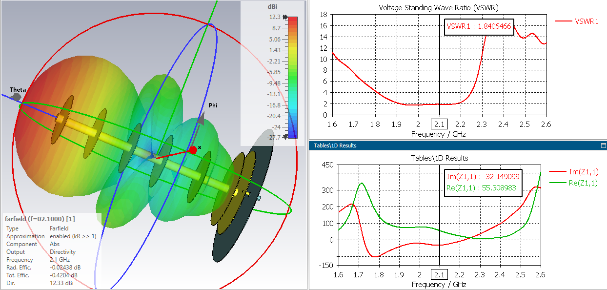
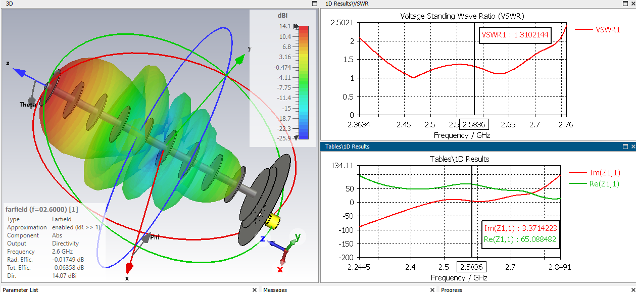
...the first image is for the (central) frequency of 2600 MHz (in red) and the second for the (central) frequency of 2100 MHz
 1 person likes this
 -
This is not what your tray looks like above....!!!
-
Yes, I think this would be a solution...!!!
-
What is this new decision?
-
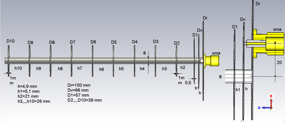
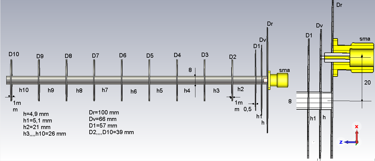
How real can these dimensions be for the patch yagi antenna...???
,,,these are according to the website...https://3g-aerial.biz/en/disk-yagi-antenna
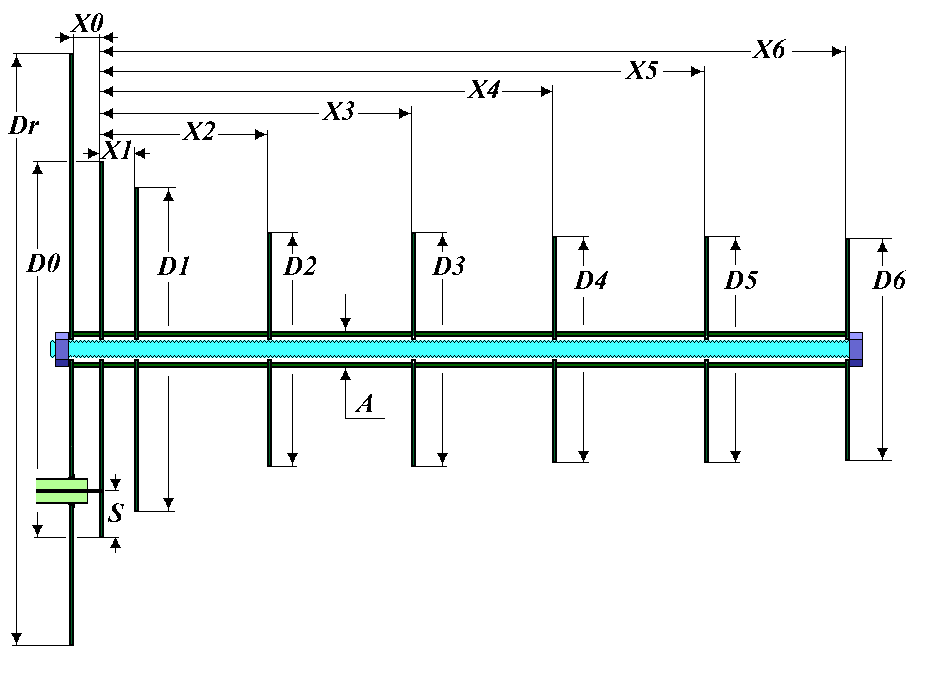
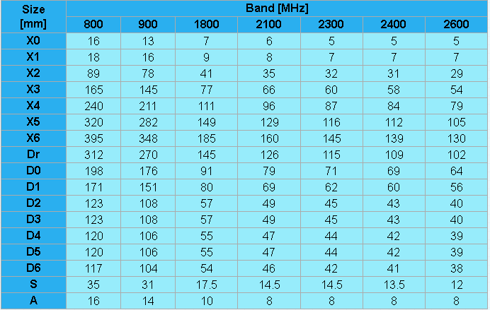
I think these dimensions need to be checked, which I will try below....I think I'll start with the antenna for 2100 MHz....

-
Bester antenna variant(2,4---2,7 GHz) with an N-P245 connector...

 1 person likes this
 -
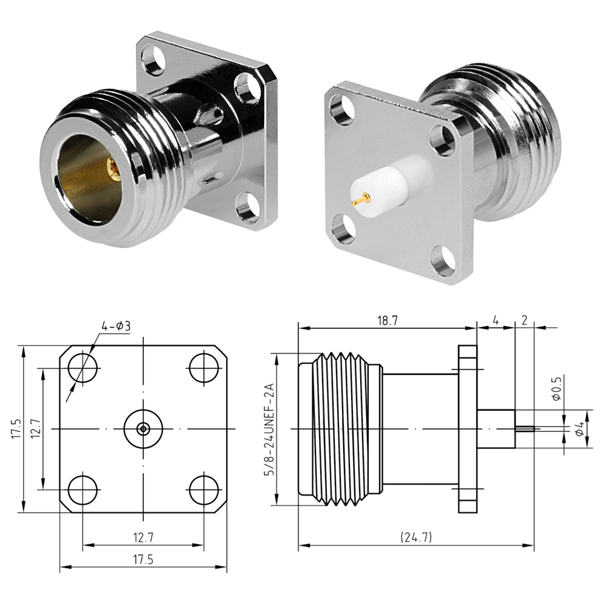
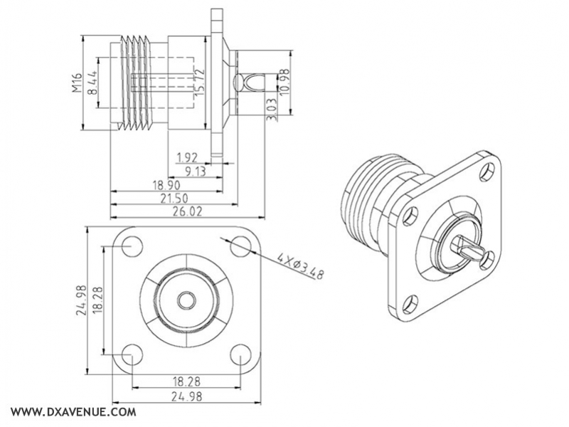
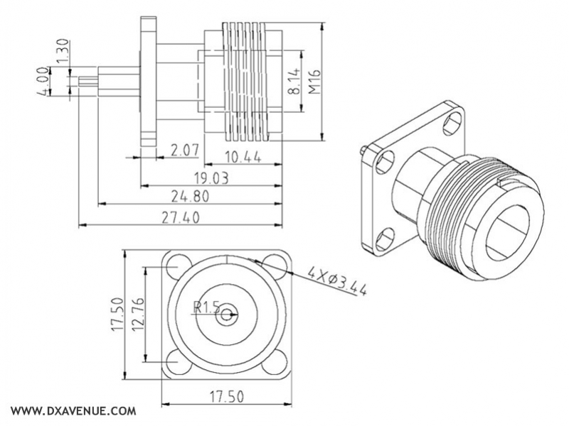
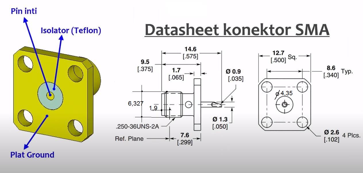
N-type socket / female N-P245 instrument flanged RF connector, for soldering, extended dielectric, 50 ohms
The N-Type connector was developed in 1940 at Bell Labs by Paul Neill, and the" N " in the connector's name appeared due to the first letter of his last name. Initially, the connector was developed for frequencies up to 1 Gigahertz, but later its potential for use was revealed at very high frequencies reaching 11 GHz, and thanks to the subsequent refinement by Julius Botka of Hewlett-Packard, the connector was used in systems operating at frequencies up to 18 GHz and can rightfully share the glory of one of the most popular devices in the world today. the most common high - frequency connectors with its predecessor-UHF. The connector has not found much recognition among radio amateurs and civilian users, but it has gained constant popularity among professionals and is used in mobile communication infrastructure, wireless data transmission (WiFi), paging and cellular communication systems, as well as in cable TV networks, standardized according to the MIL-C-39012 protocols.

-
On 12/26/2024 at 10:07 PM, dumser2 said:Help me choose a 450MHz omnidirectional, compact FR4 or collinear antenna.
Can you post technical details for your antenna...???
,,,possibly CST-file....??!!!
-
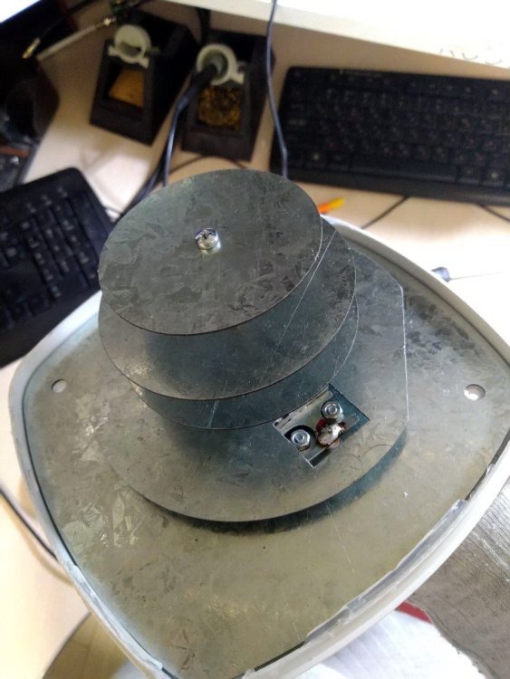
,,,okay, and inside it has disc elements...???
-
,,,a new YouTube...
-
On 5/5/2019 at 10:52 PM, clanon said:What size is that pannel...? average...
,,,this is...

 2 people like this
 -
,,,goto Modeling>History List>delete all farfield
,,,install another frequency>>>
-
When you increase the frequency range, you must delete the old frequency range and install the new one."
-
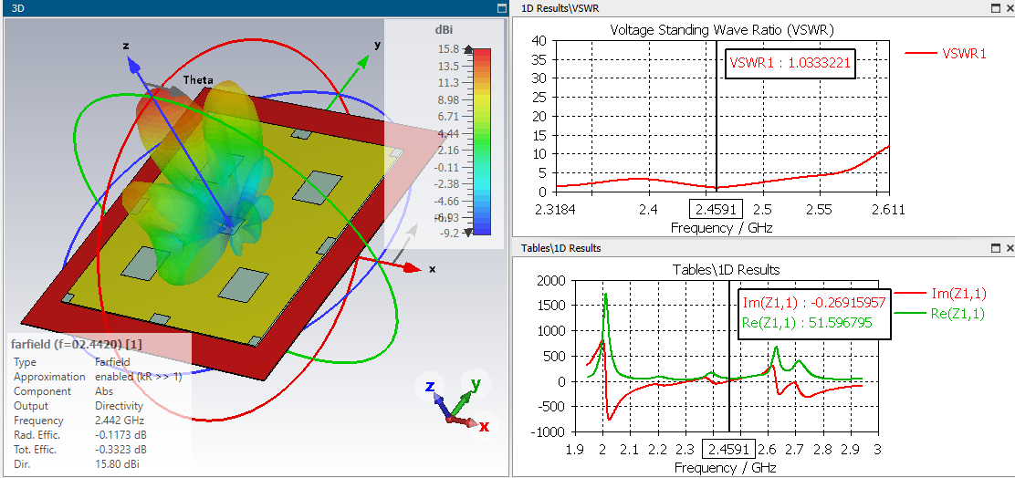
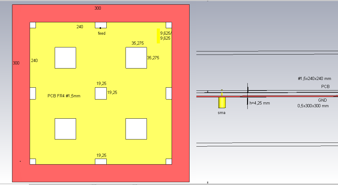
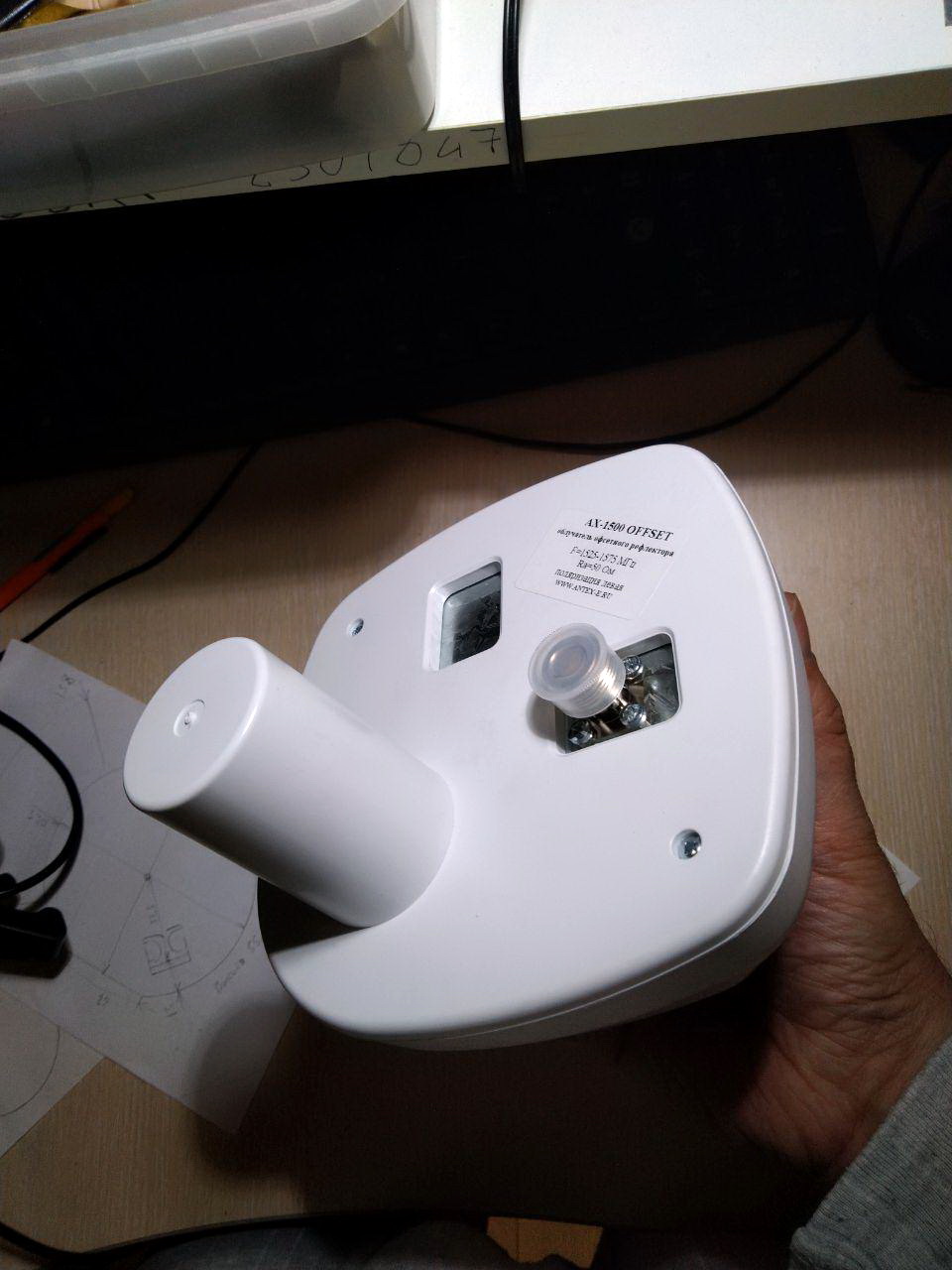
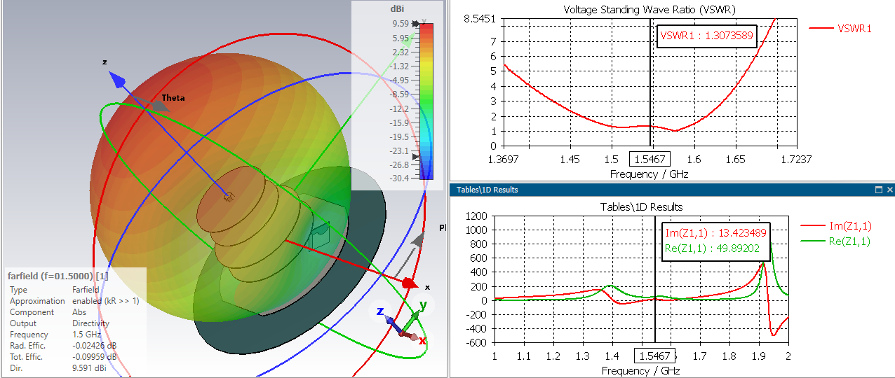
,,,another type of Bester Antenna ...
Article numberAX-1500 OFFSET BOX
Input impedance, Ohms50
Overall dimensions, m0, 145x0, 145x0, 154
Permissible power, W10
Protective coatingpowdered polymer paint
SWR in the operating frequency range, max.1,3
Weight300
Casing materialABS+Polycarbonate
Irradiator materialgalvanized steel
Polarisationleft\right circular map
Operating frequency range, MHz1525 - 1575
ConnectorsSMA-male on flexible cable
Resulting gain (and bottom width) for different dish diameters25,6dBi ; 16,8dBi ; 17,6dBi ; 21,1dBi ; 24,3dBi
The resulting gain and level width of the radiation pattern is 3dB0.55 m 16.8 dBi 23 gr. 0.6 m 17.6 dBi 21 gr. 0.9 m 21.1 dBi 14 gr. 1.3 m 24.3 dBi 9 gr. 1.5 m 25.6 dBi 8 gr.
Native gain, dBi10
Width of the DN lobes in the E-plane (horizontal), °110÷120
Width of the DN lobes in the H-plane (vertical), °110÷120

 1 person likes this
 -
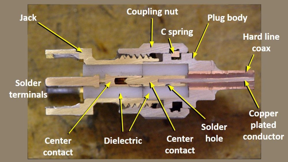
,,,inside(section) of the connectors...
 1 person likes this
 -
1 hour ago, prda said:Can I get the dimensions of this antenna and what material it is.
,,,dimensions are shown in the images above...!!!
1 person likes this


in Antennas for 2.4 GHz band
Posted
It's still simple, I don't know why you don't understand...!!!???