Register now to gain access to all of our features. Once registered and logged in, you will be able to contribute to this site by submitting your own content or replying to existing content. You'll be able to customize your profile, receive reputation points as a reward for submitting content, while also communicating with other members via your own private inbox, plus much more! This message will be removed once you have signed in.

Harry36
Members-
Content count
187 -
Joined
-
Last visited
Posts posted by Harry36
-
-
-
2 hours ago, Admin said:,,,what does cst2023 have in addition to the previous versions...???
https://www.3ds.com/products-services/simulia/products/cst-studio-suite/latest-release/
-
-
-
On 15.09.2022 at 1:35 PM, eco32 said:What else, what profit can it give.
.thumb.jpg.42c4ee633bb301bb0133545683c5801e.jpg)
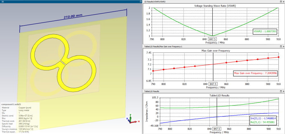
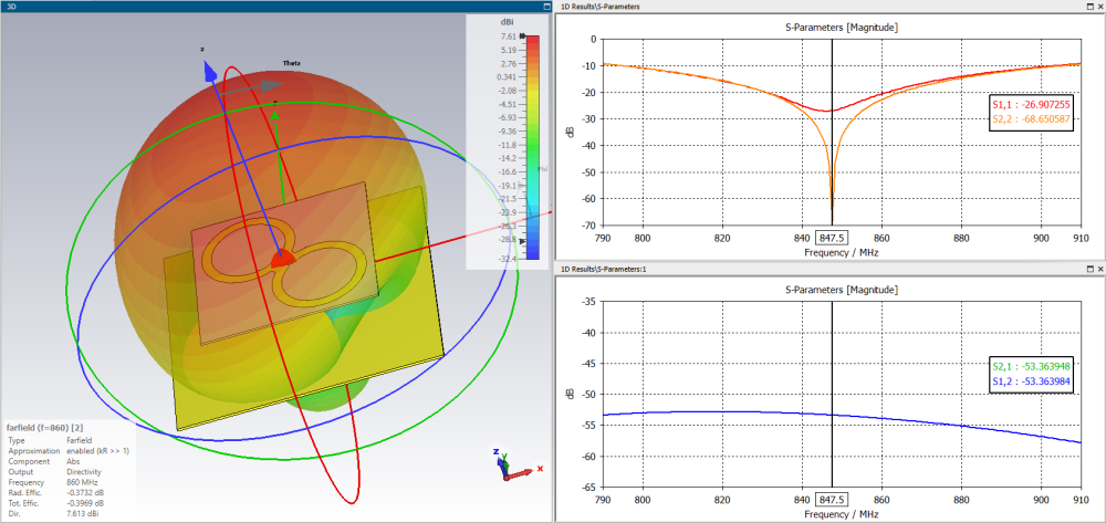
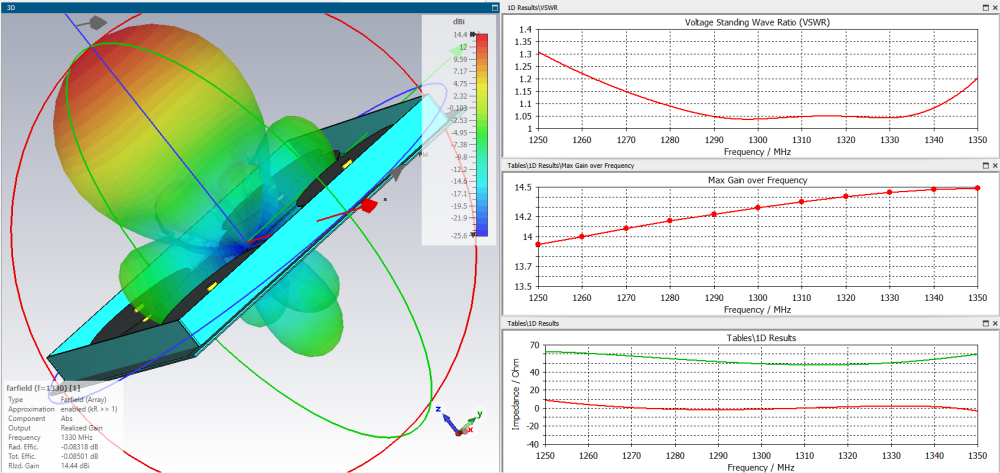
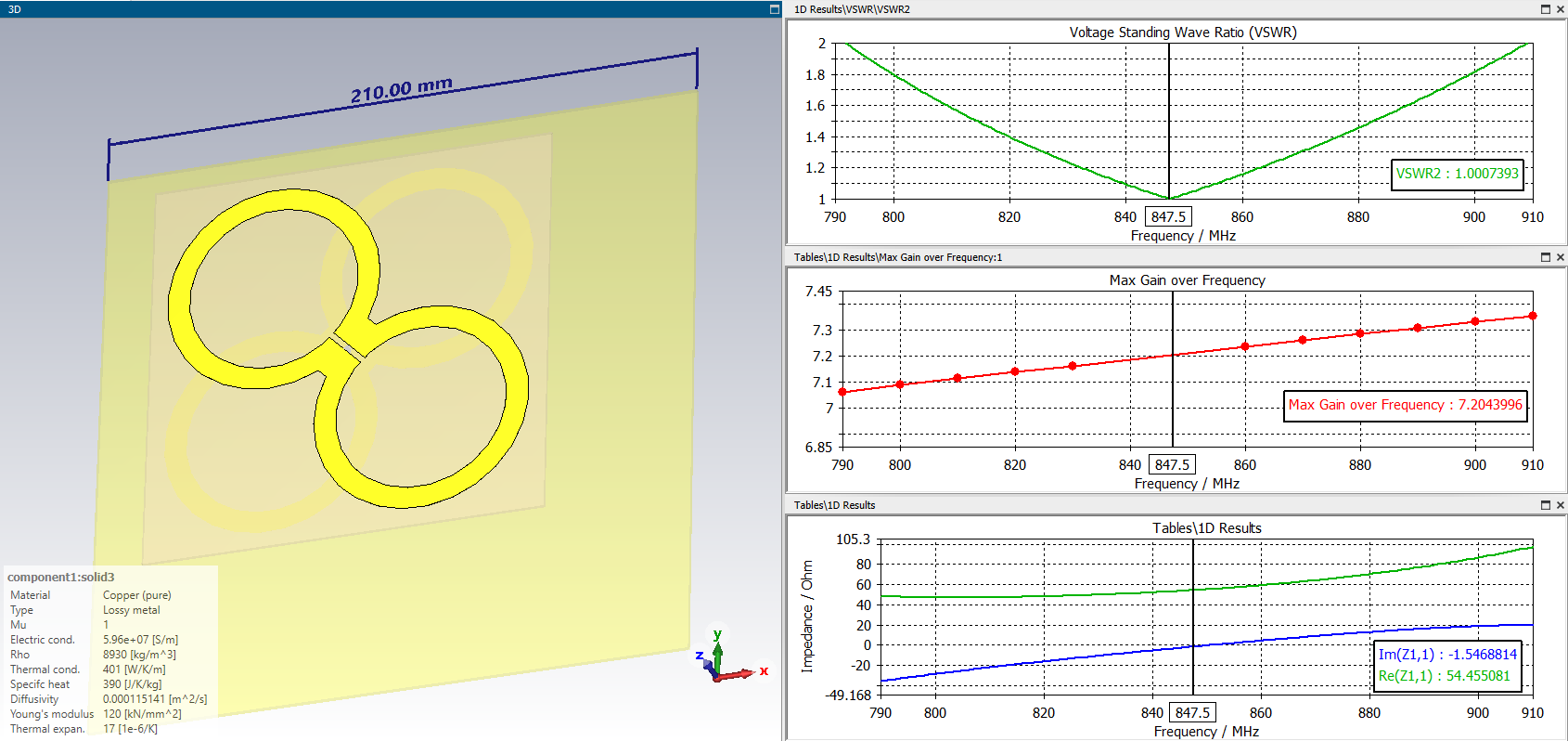
Figure 2 in the quote shows the dimensions of the antenna for LTE800 band (min swr~ 850 MHz), it is made in the form of two antenna sheets on different sides of FR4. the dimensions match the simulation quite well.
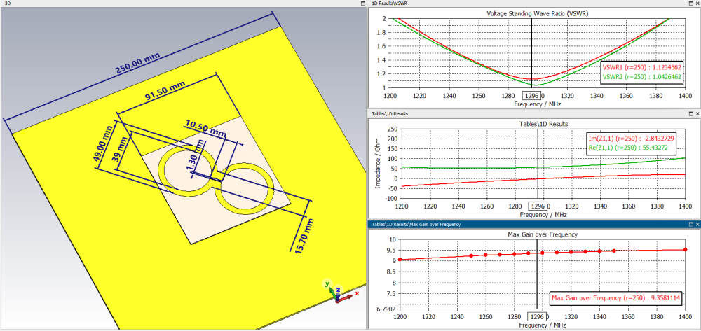
In order to make a similar antenna for a frequency of 1296 MHz, you need to reduce the dimensions by a factor of 1.52 dimensions.
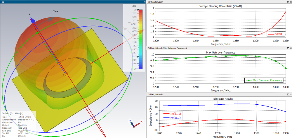
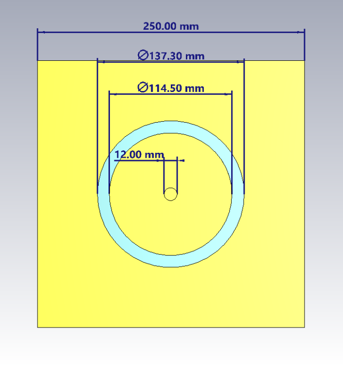
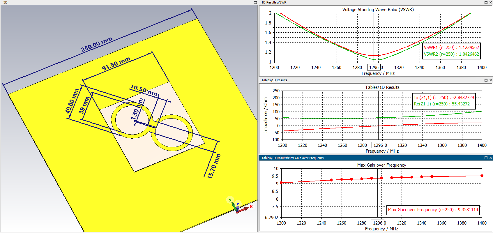
The antenna has a fairly low gain of ~7.2 dBi. This is due to the minimum size of the reflector. By increasing the reflector to 250x250 mm, you can increase the antenna gain to 9.5 dBi at the same time, if you do not change other dimensions, the SWR also increases to a value of 1.1. tFR4=1mm, tCopper=0.018, H=28.4.
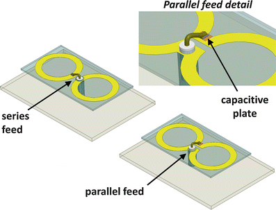
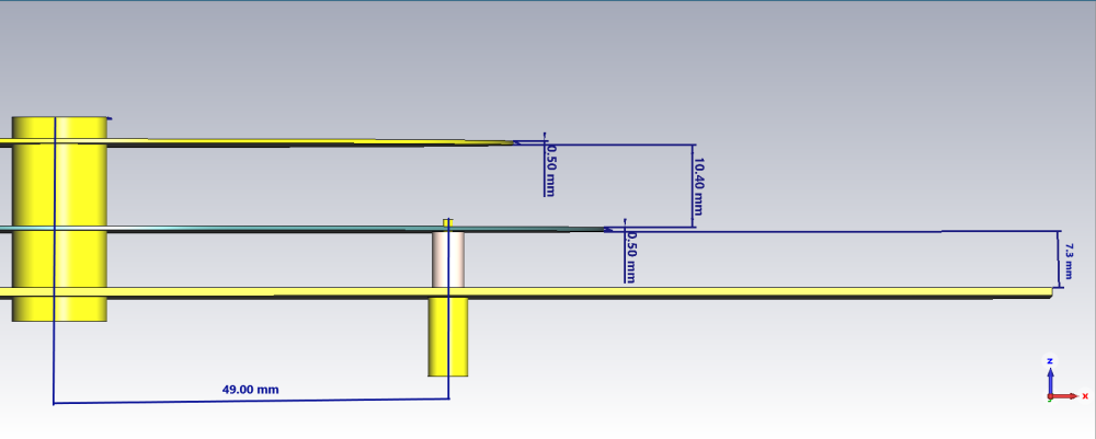
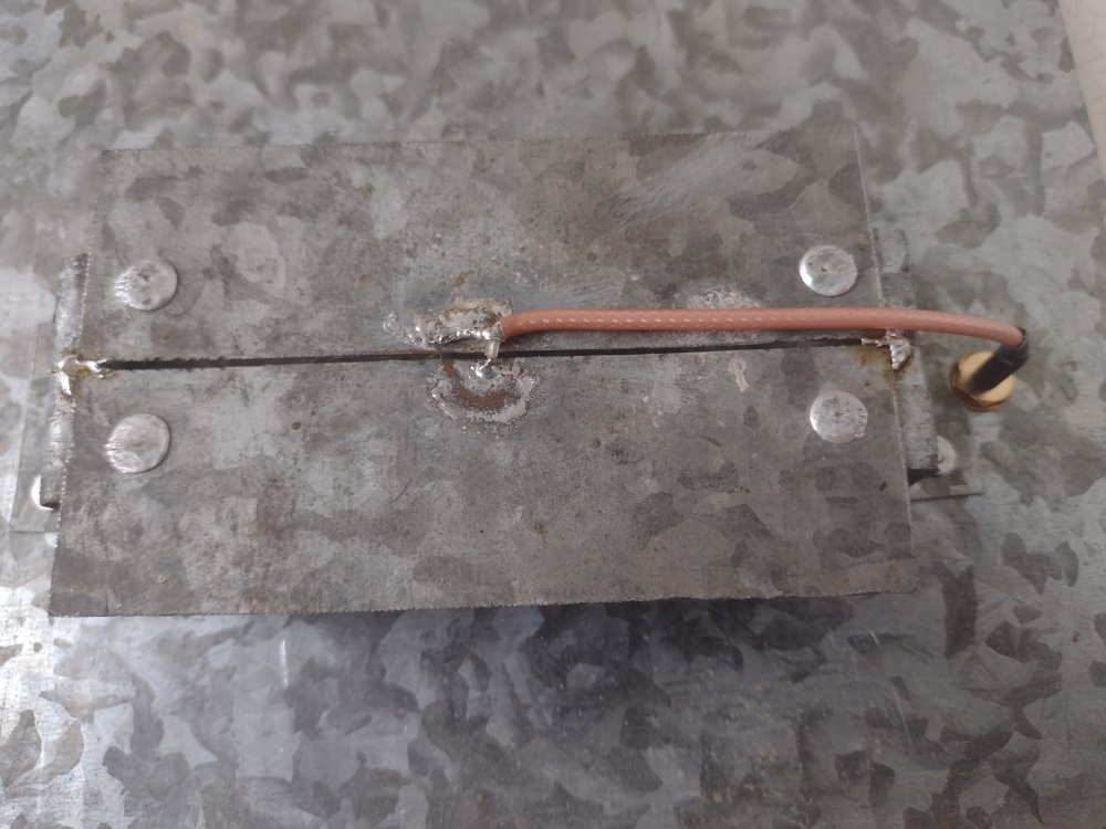
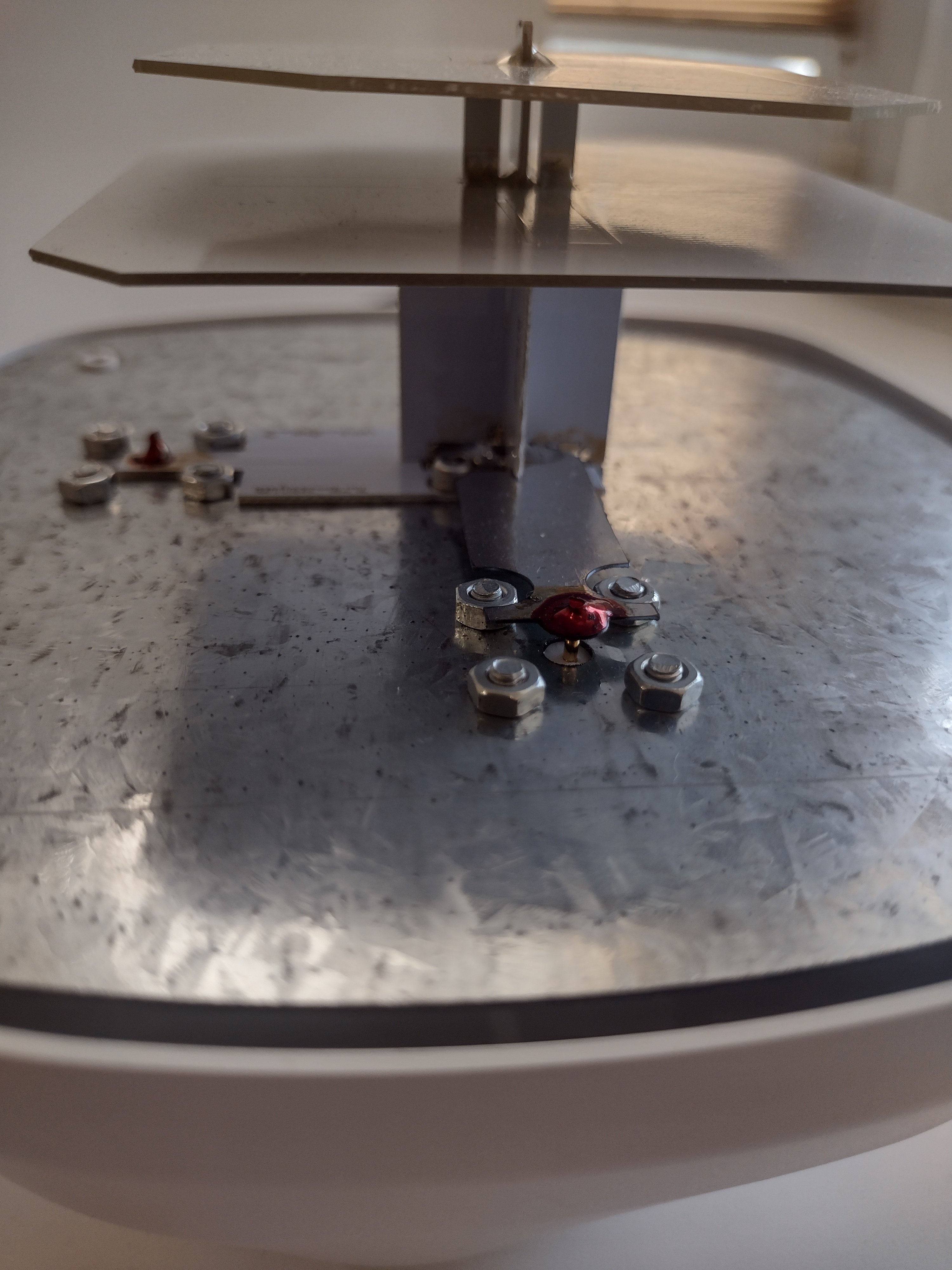
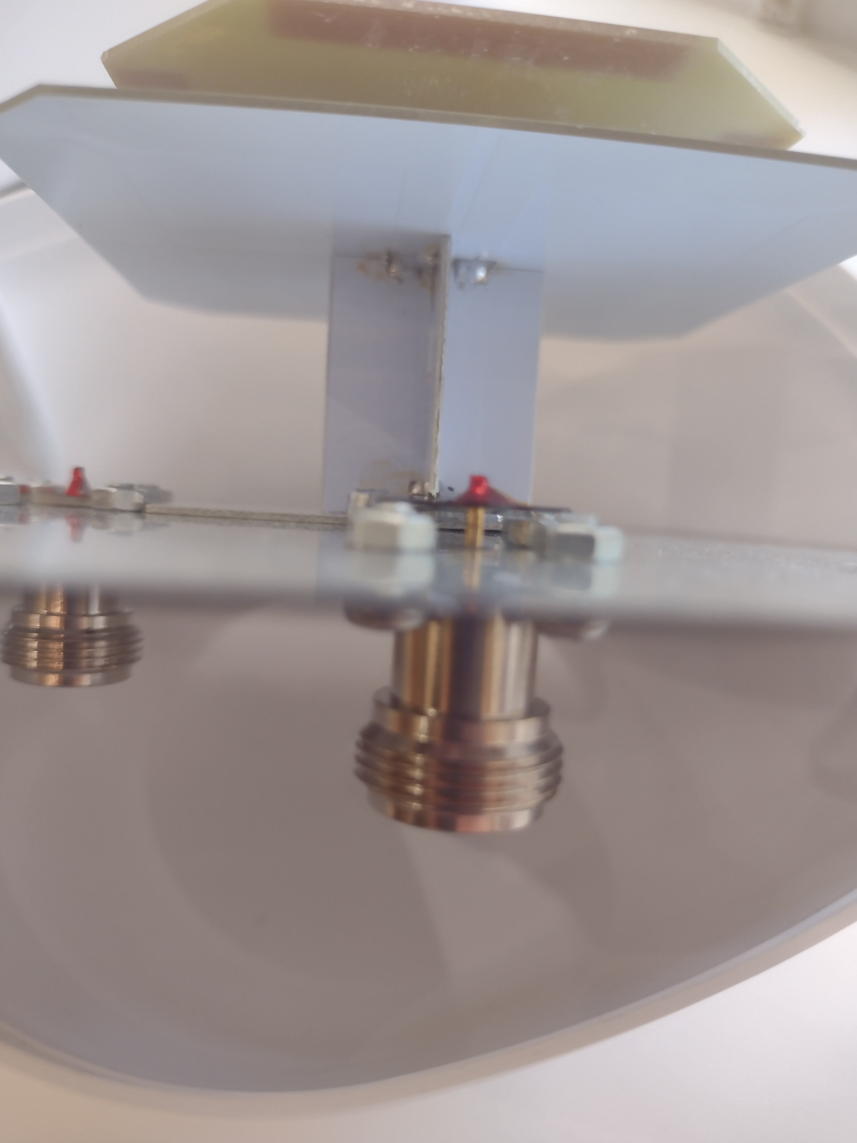
Antenna connection is shown in fig. 1 quota is performed without balancing, this is a wrong connection. The cable must be soldered from the side of the web of one of the antennas (upper or lower) and brought along the arc of a circle to the middle of the frame (circle), then lowered onto the reflector, where to install the connector. Cable use RG-316.
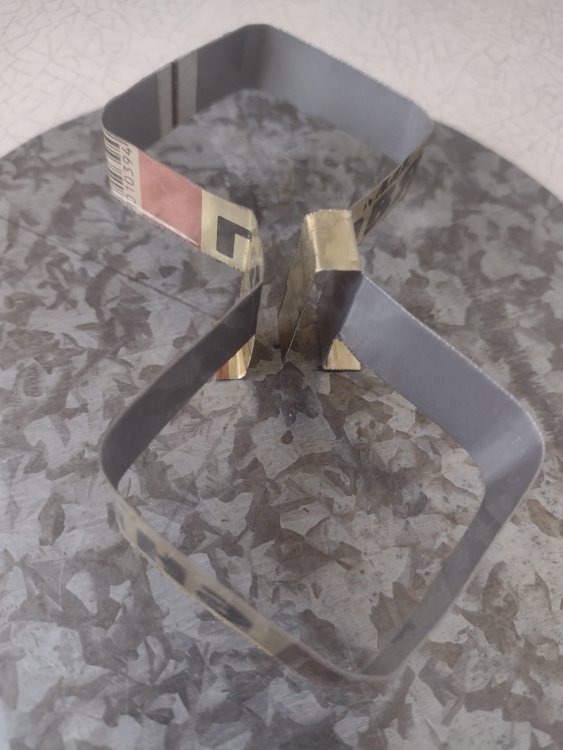
FR4 is a rather unstable material and antennas made from it very often fall outside the calculated range. for home production without appliances, it is not entirely suitable. it may be easier to make an antenna out of metal. For example, by type BDM. reflector and two disks. this will give a fairly wide bandwidth at a very low SWR and will forgive manufacturing errors even with a hand tool.
or stack 2x2
or dipole from metal can dia=66.3 mm
")
 1 person likes this
 -
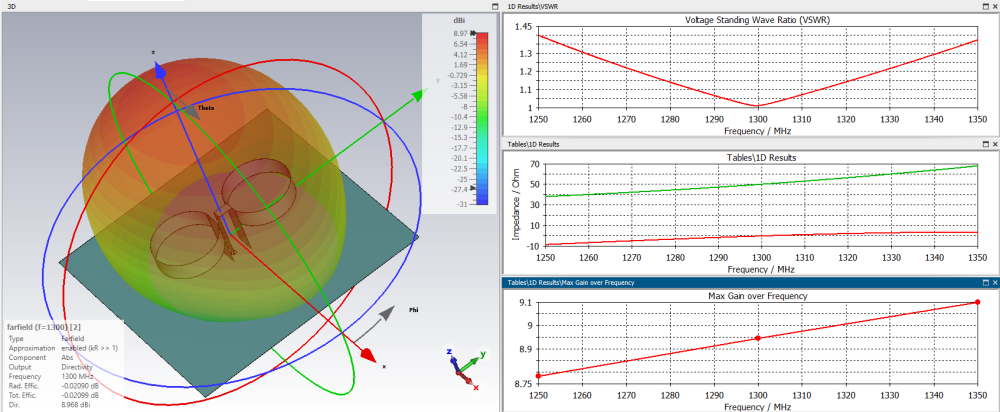
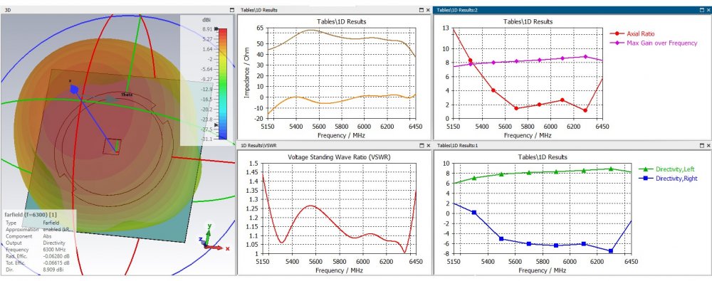
7 hours ago, Admin said:,,,it is also possible like this, circular dipole...
It's not dipole, this is biguad + balun )
-
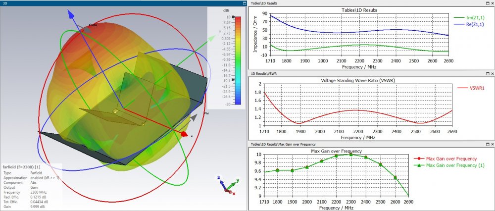
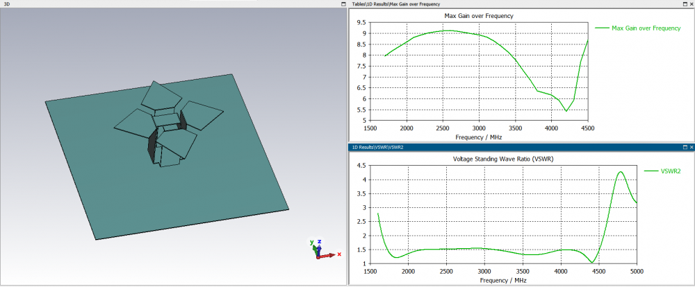
19 hours ago, Dr. Pepper said:The slot dipole with V cut outs like an batwing antenna, not as good for broadband application but a little more compact than the slot dipole and a good gainer. Here an example for a wifi antenna
Try to draw a balancing device in the model.
1 person likes this -
 1 person likes this
 -
-
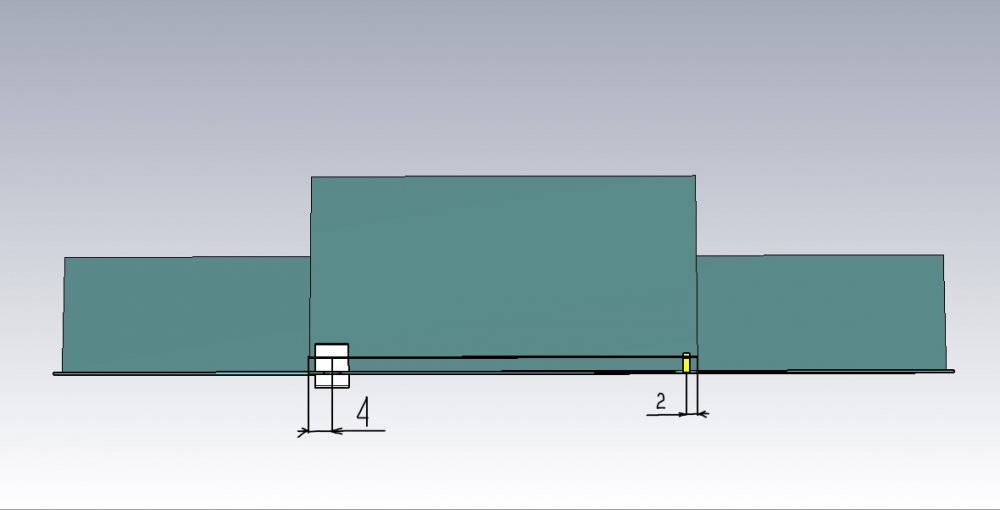
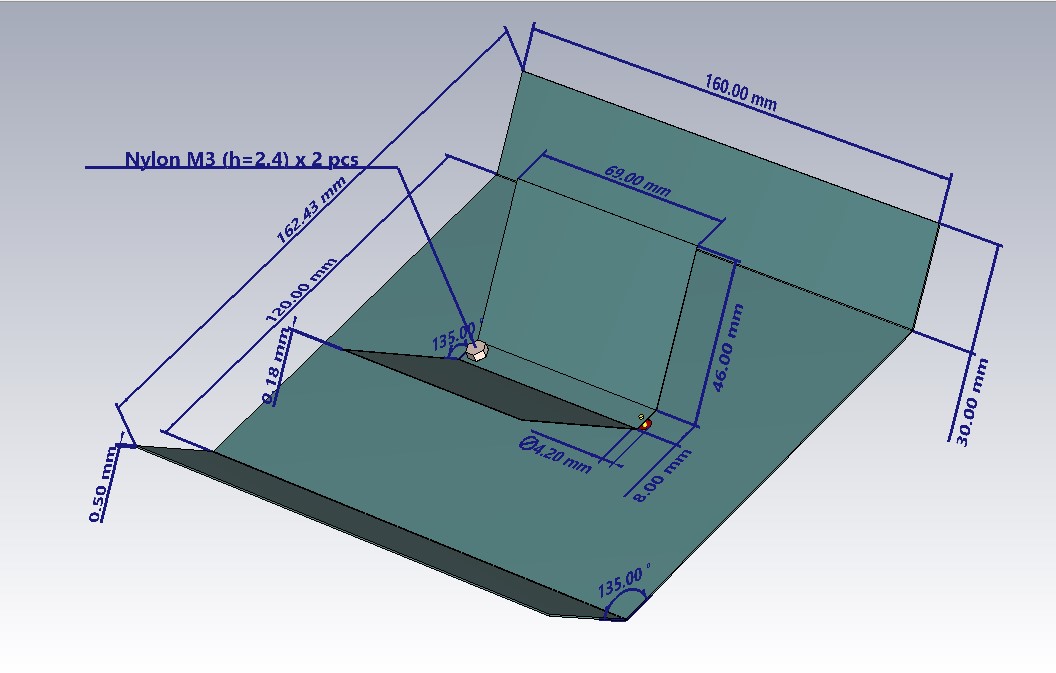
3 hours ago, Admin said:,,, that's what it would look like ... !!!
This is 50 Ohm version.
-
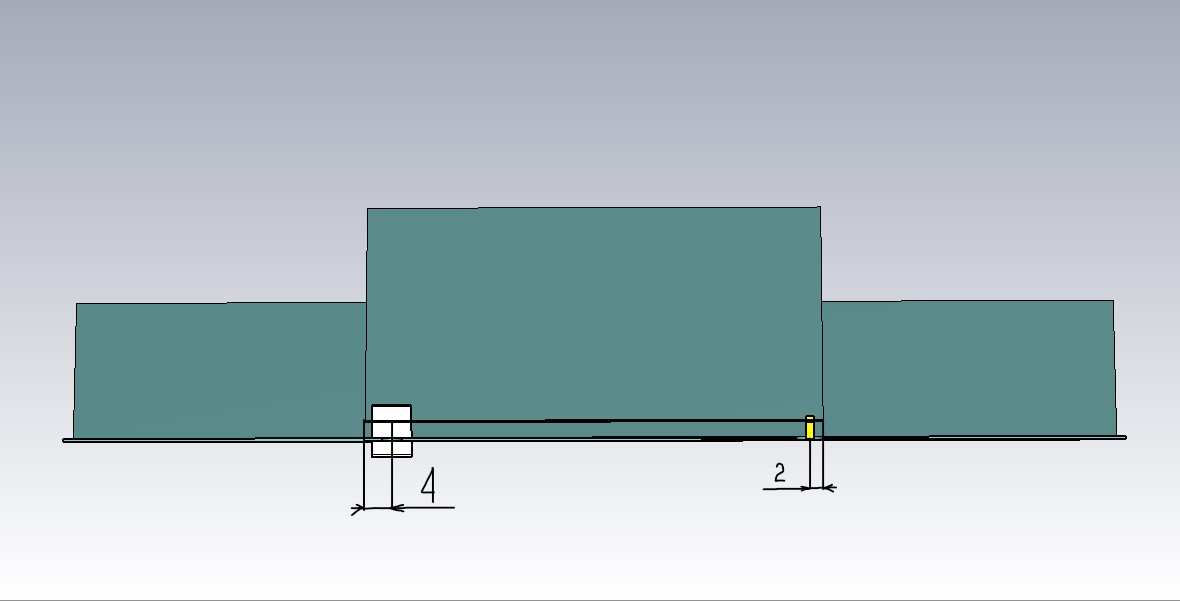
edge feed - 2mm
height 2.4 mm
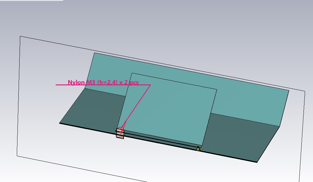
nut m3 (h =2.4) nylon 2 pcs
screw m3 (l =10 mm) nylon from edge 4 mm

 3 people like this
 -
2 people like this -
what do you think about the losses of copper and galvanized steel?
0.01 dBi?
 2 people like this
 -
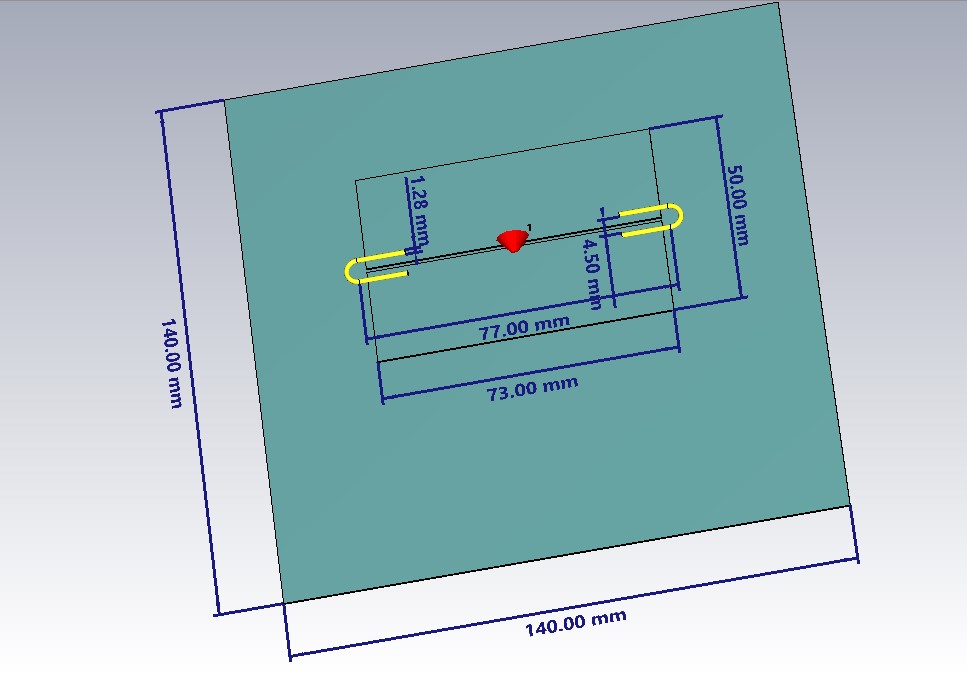
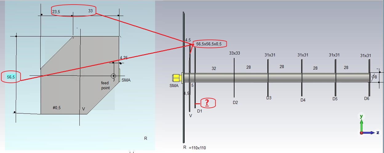
On 29.05.2022 at 11:07 AM, Admin said:D1=45x45mm
I don't get the specs for that size.
-
-
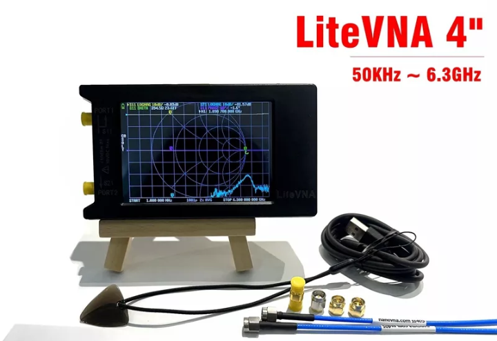
6 hours ago, Dr. Pepper said:I have a SAA2 NanoVNA which costs about 80 Euro but can only measure up to 3 GHz, if you want to measure up to 6GHz you have to spend about the double for it. I think such a VNA is the most basic tool to measure any antenna. It gives you the ability to correct the antenna that it works like it should.
LiteVNA costs about $80 for the 2.8-inch version. https://aliexpress.ru/item/1005003802185241.html?spm=a2g2w.productlist.0.0.616ed52d8qmiOH&sku_id=12000027216067991
and about $100 for the 4" version https://aliexpress.ru/item/1005004126788962.html?spm=a2g2w.productlist.0.0.616ed52d8qmiOH&sku_id=12000028123208491
The prices for these devices are very affordable and they work quite accurately.
2 people like this -
 1 person likes this
 -
-
Structural aluminum dipoles are very expensive to make at home, and can be made even easier with galvanized steel.
 1 person likes this
 -
IMHO for lte1700-2700 very nice

-
38*38*6 mm
steel
-
make directors from a core of a copper cable for electrical wiring (see the typical diameter from the wire section). The directors holder can be made from a thin strip cut from galvanized steel, like the butwing itself, the directors can be soldered onto the holder simply and quickly. you can fix the holder to the "batwing" racks with rivets.
and I would slightly increase the size of the antenna so that the maximum gain falls on the desired frequency (2.45) or to capture the entire band 1700-2700 in SW<2...1.5.
the size of the antenna (more precisely, the reflector) will directly determine the gain
") 1 person likes this
1 person likes this -
great job!
there's still some tuning left
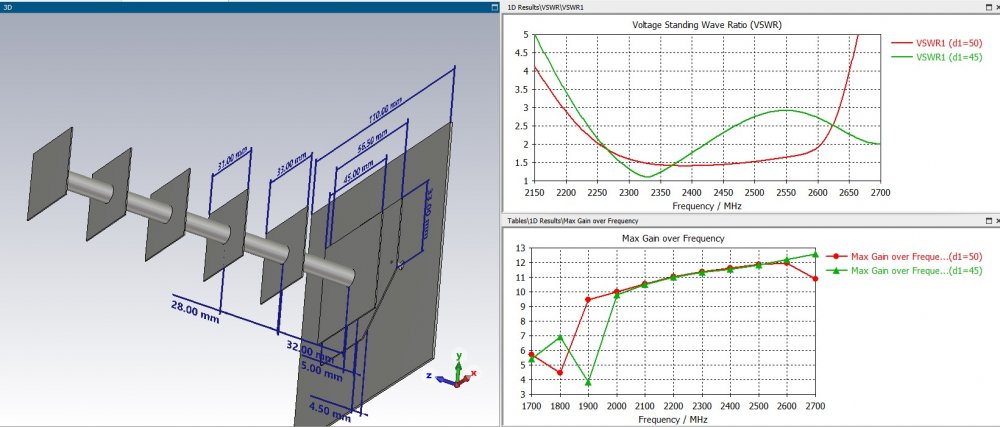
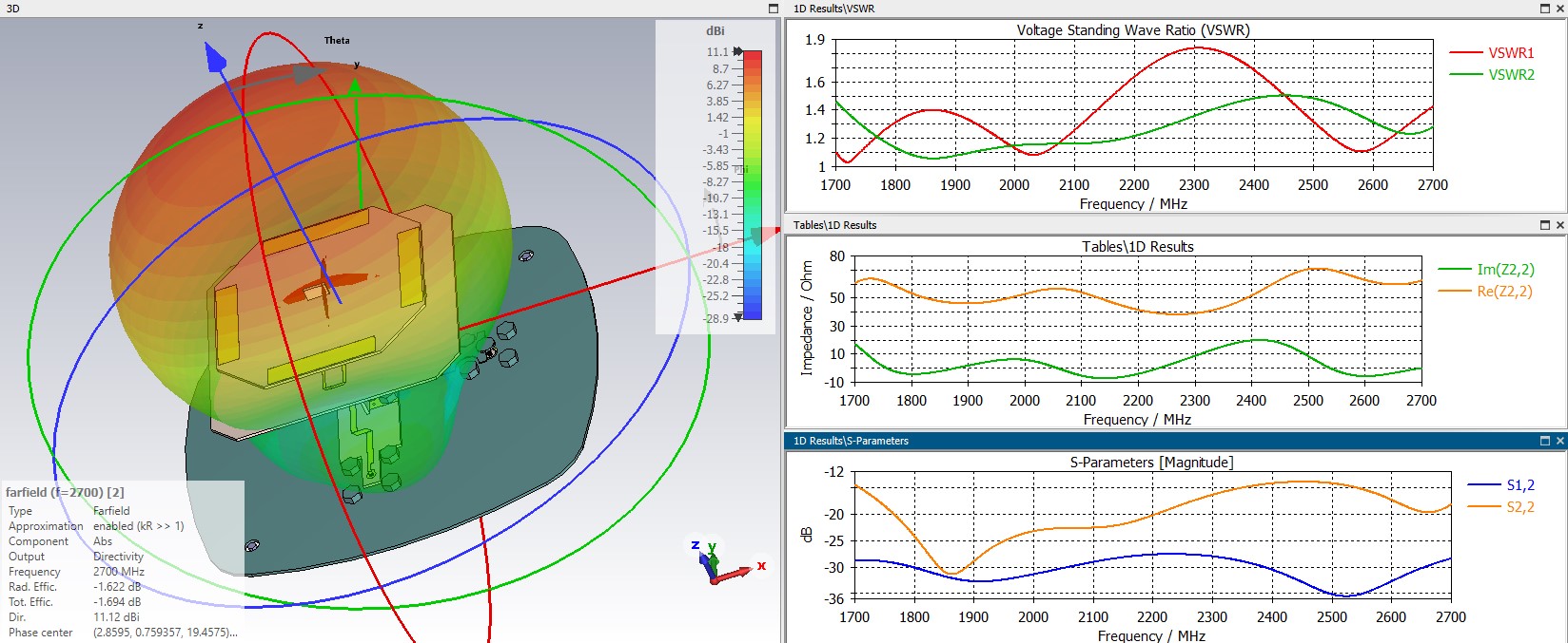
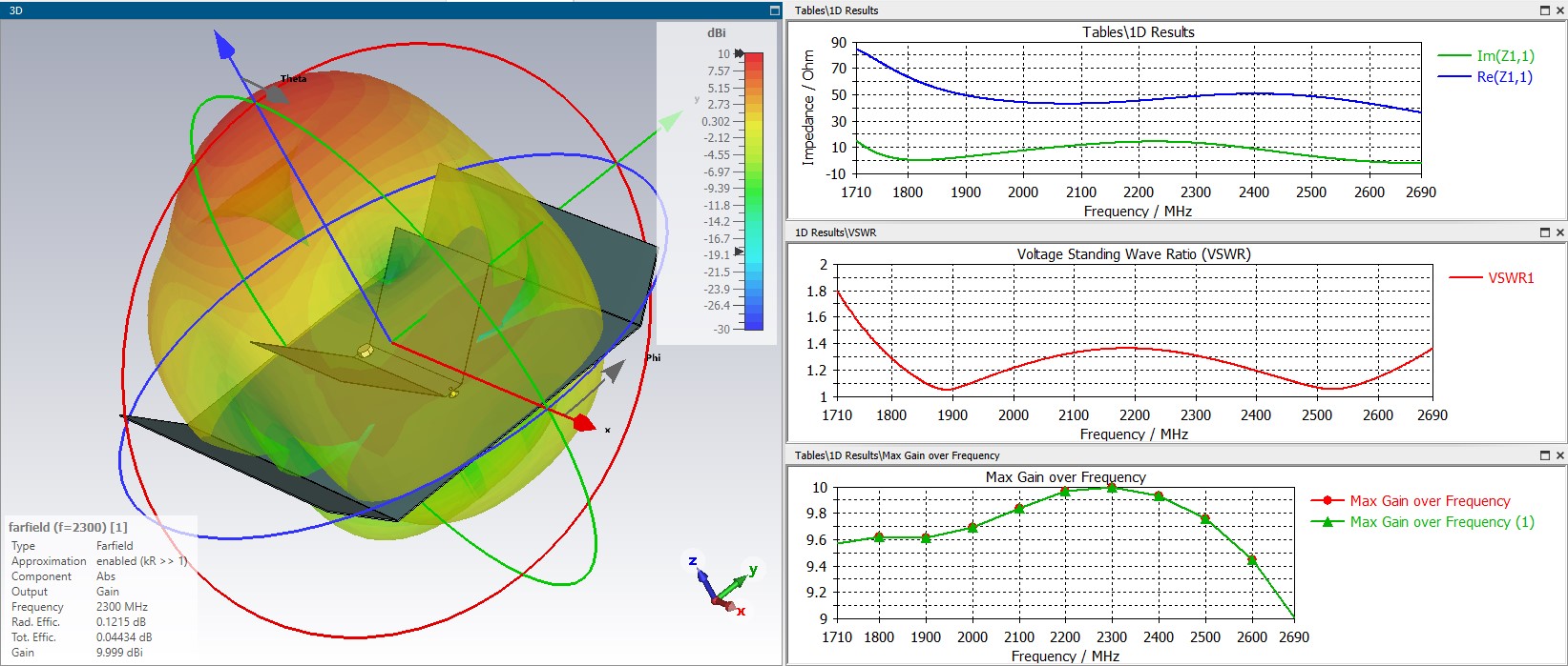
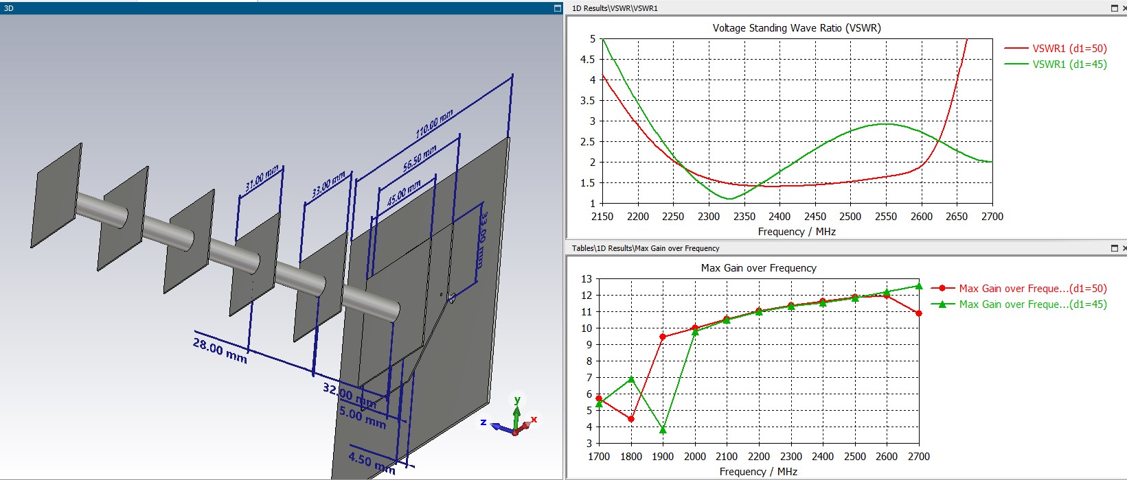
in the region of 2 GHz there is a break in the SWR graph. change the dimensions of the directors (diameter and height above the batwing, it is not necessary to do everything at the same height) and you should get a broadband antenna like I have on Lan23
Making a narrowband antenna is not so difficult, but stretching the bandwidth to the maximum is much more interesting
1 person likes this -
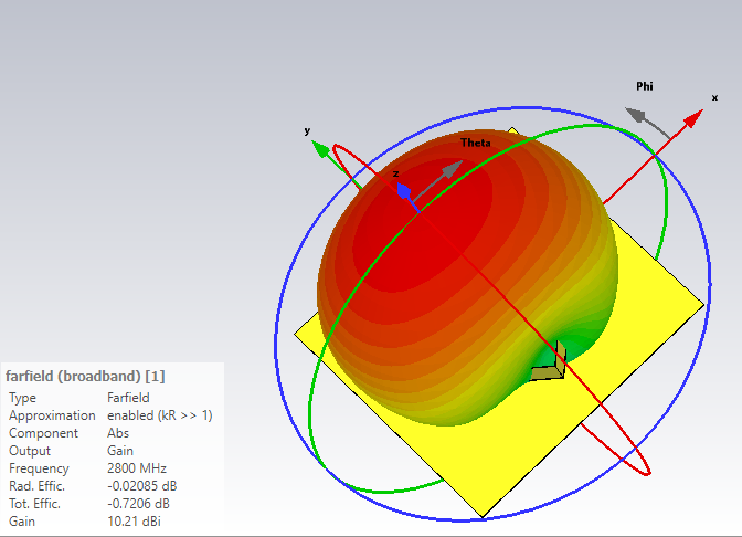
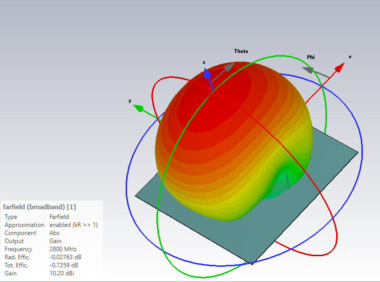
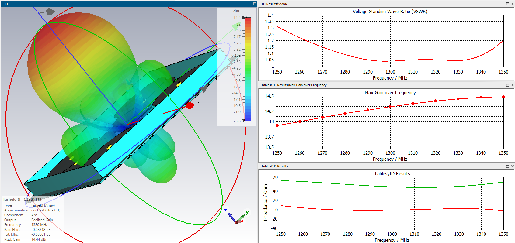
You don't have sidelobes on the x-axis and quite large on the y-axis. Try resizing the reflector ;-) , this should help flatten the radiation pattern and raise the gain.You don't have X-axis sidelobes and quite large Y-axis ones. Try resizing the reflector ;-) , this should help flatten the radiation pattern and raise the gain (energy from the sidelobes will go into the main direction). The antenna is symmetrical and requires a Balun to connect the coaxial cable. It seems to me that this has nothing to do with the loop antenna (Kharchenko's bi-square), this one can be considered as a broadband dipole with a shunt or as a slot.
One of the simplest options for a balun is to lay a cable along the slot to the zero potential point (connecting the two halves of the emitter sheet) and leading it to the side of the reflector.
But this option requires a relatively small diameter cable, preferably with a TEFLON dielectric and an SMA flange crimped on it. Not everyone has such a cable. it seemed to me that at home it is easier to make the balun suggested by me on the previous page. You can multiply the dimensions in the project by 2.5 - 3 and get the dimensions for the range 1.7-2.7
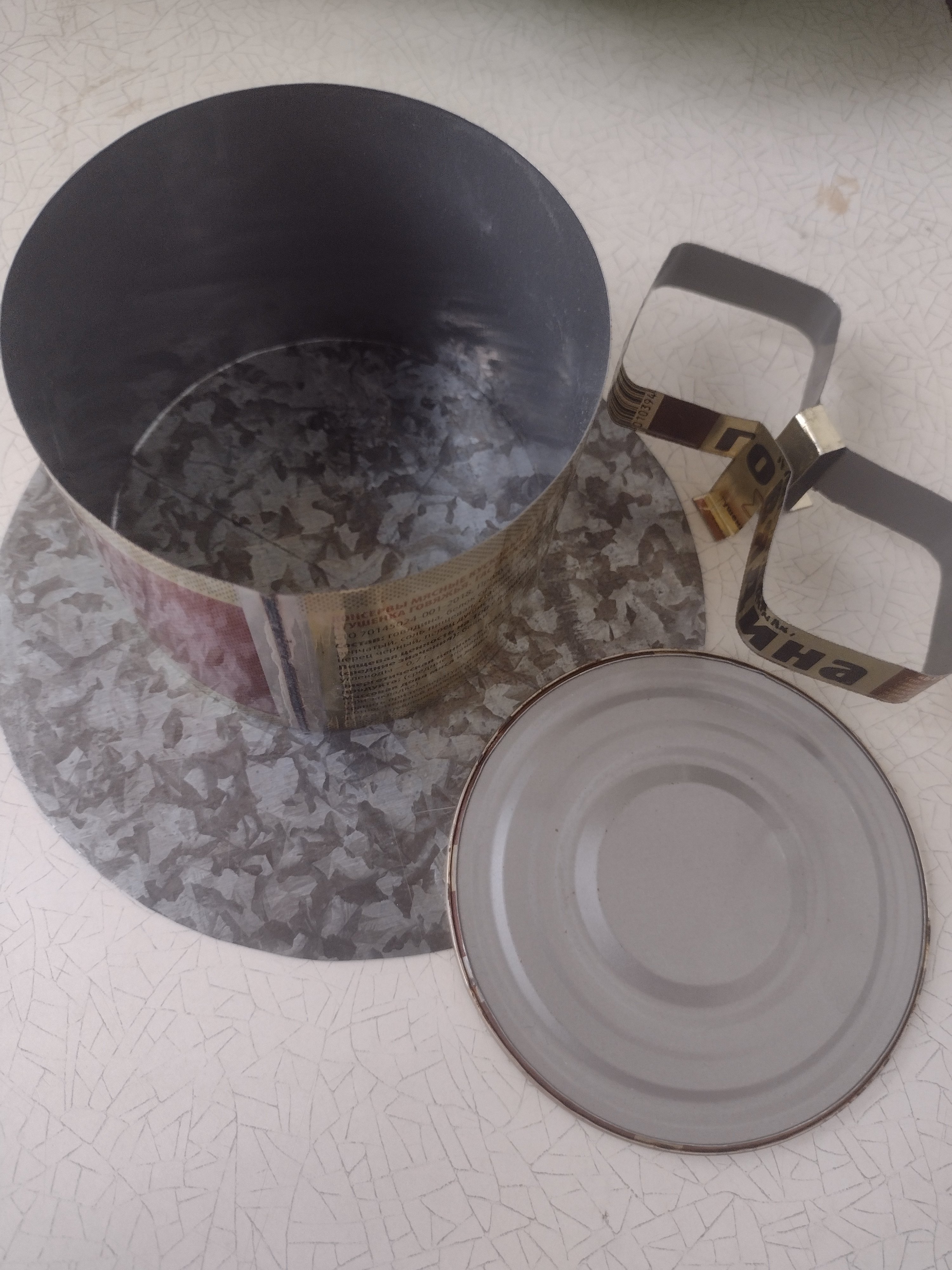
If you adjust the dimensions, then the structure fits into the perimeter of a metal can with a diameter of 99 mm. This is a very simple and quick solution for home-made from scrap materials.
 1 person likes this
.jpeg.a2e3dd70b1aed51c1b9127716db31101.jpeg)
.jpg.470cb116edfb1b3d38e6d37bc9695387.jpg)


in Antennas for mobile communications
Posted
version? 22 or 23?