Register now to gain access to all of our features. Once registered and logged in, you will be able to contribute to this site by submitting your own content or replying to existing content. You'll be able to customize your profile, receive reputation points as a reward for submitting content, while also communicating with other members via your own private inbox, plus much more! This message will be removed once you have signed in.

clanon
Members-
Content count
844 -
Joined
-
Last visited
Posts posted by clanon
-
-
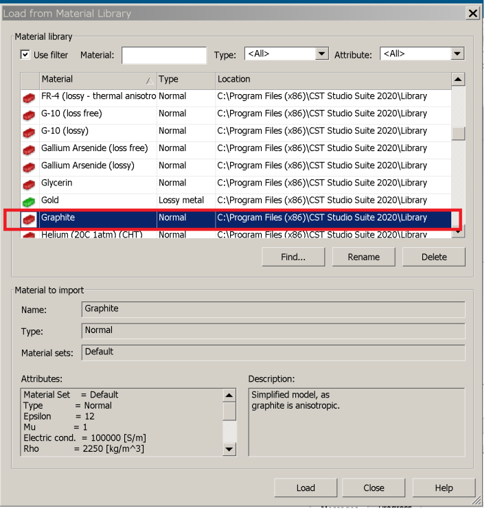
On 8/3/2024 at 4:43 AM, Aksonx2 said:. Please tell me what parameters should be entered when calculating the antenna to calculate the antenna if . Is it mounted on a carbon fiber base? Does carbon have characteristics similar to metal for calculations in the program?
-
5ghz band at 5 km gonna need some REAL EFFORT (Sector antennas and Power-sensitivity on AP)
-
-
On 6/14/2024 at 2:08 PM, tomasbj said:1) What are these cross patch shapes for? Directivity control, so that more gain? ... Surely the cross shape is for circular polarization achievement/improvement.
2) So... they use slot feeding mechanism?
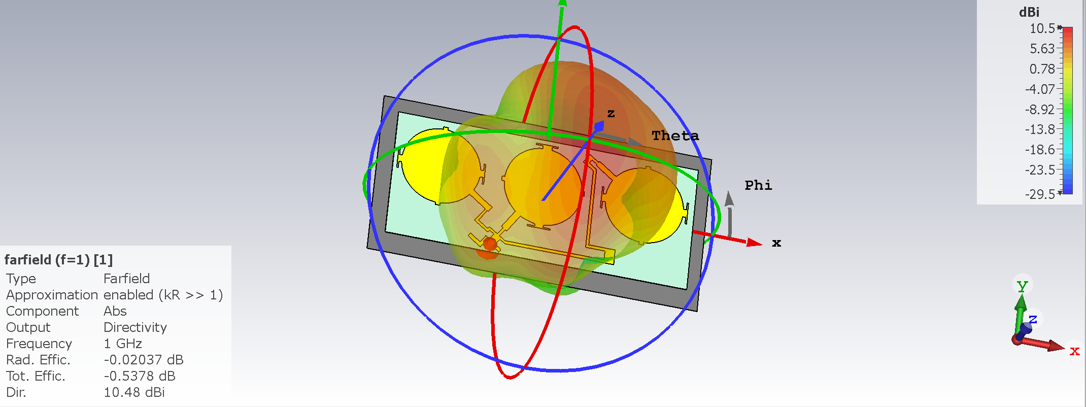
They are Circular polarized disc patchs Right hand and Left Hand without the CUTS it would go linear...
and are switched electronically from RHCP to LHCP
and EACH disc could be fed (slot feeding) the phase of signal you program (delays) to make an Electronically Scanned Array (no need to point to Each satellite , the electronics do that) AND there is BEAM FORMING too...
-
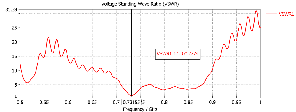
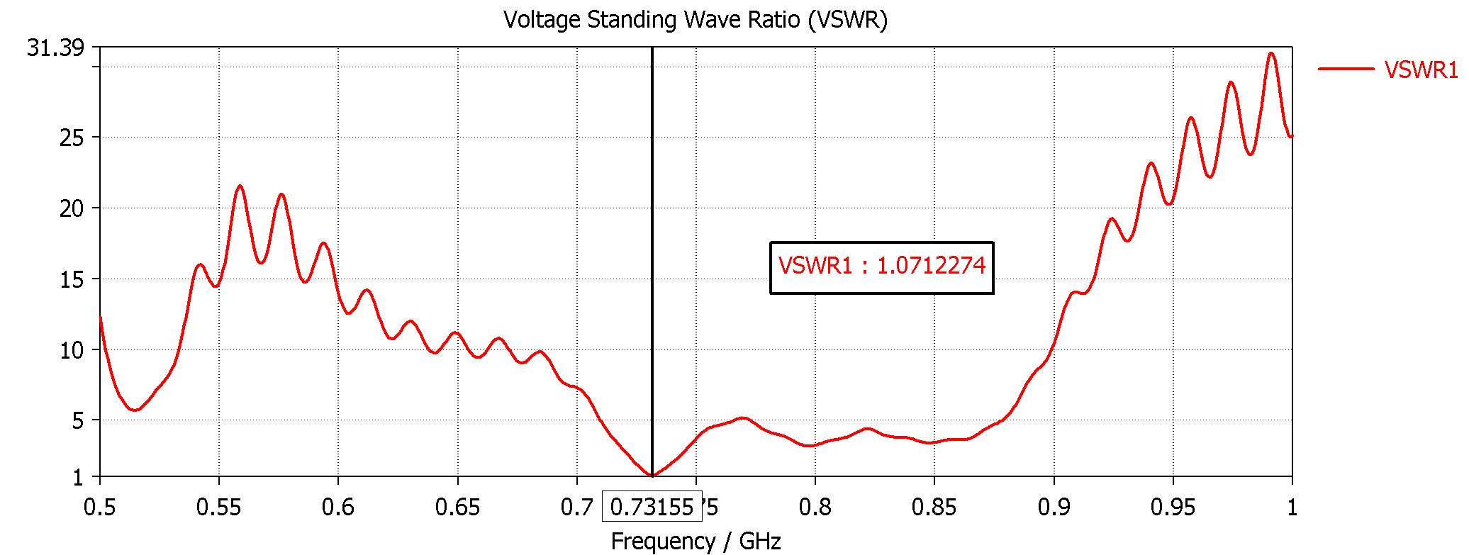
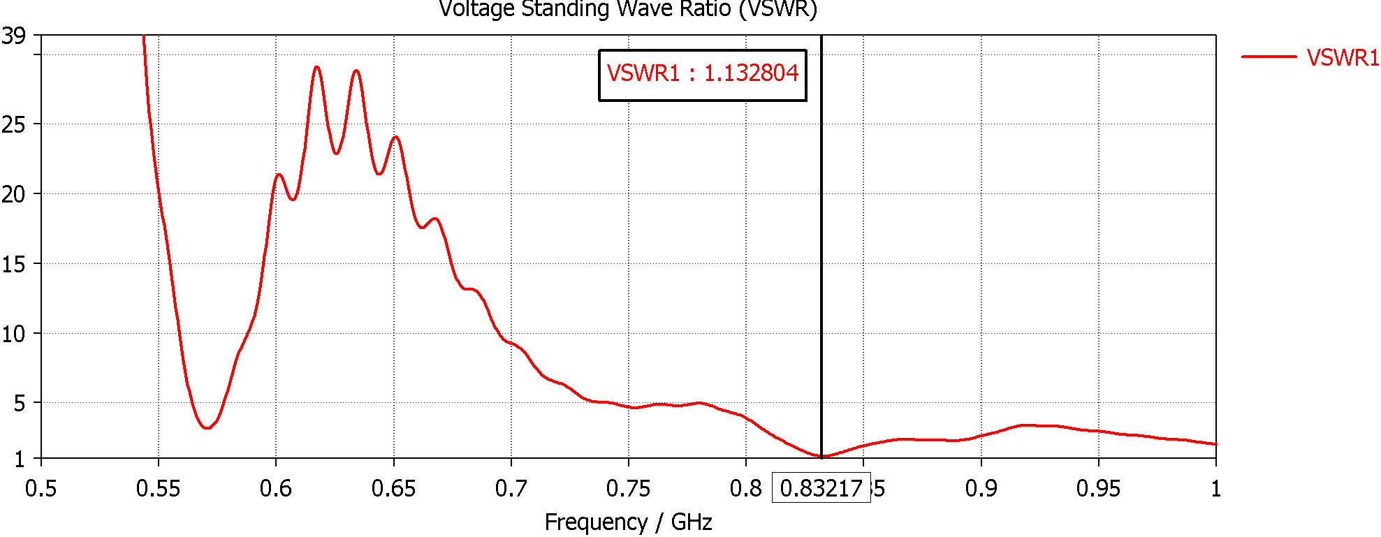
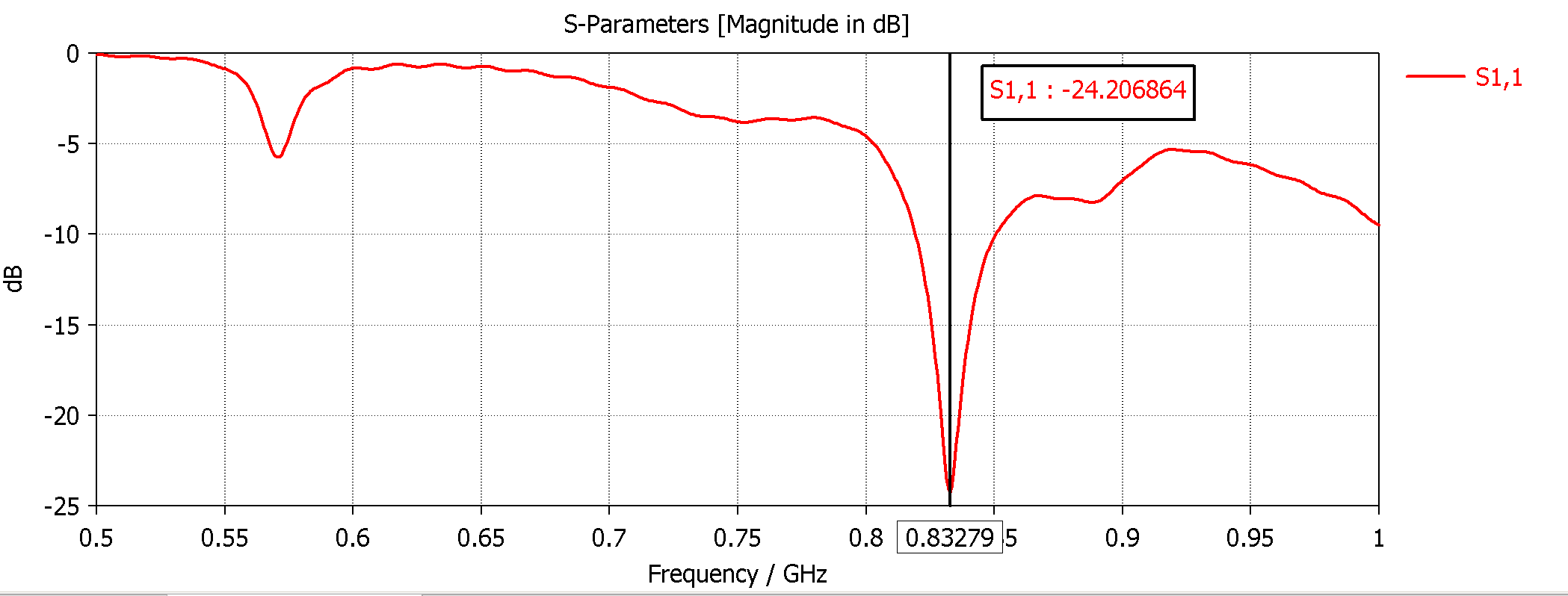
IIRC the WIRES UNDER the discs (closer to reflector) gave less reactivity ...improving VSWR...
1 person likes this -
you gonna need tubing (aluminum old TV antennas) 10 mm or more...MOST Array aren't omni , metasurfaces are a LIE...VERTICAL FRANKLIN Collineal is the way...BUT MOST I see are folded dipoles with facing on the coax...SO a SIMULATION is NEEDED for ONE DIPOLE and then multiply by at least 6-8 or 10 units and facing COAX should be calculated...for 340 MHZ and 50 mhz bandwith...
-
12 dbi omni is doable...what wideband arround 340 mhz...? (Narrow = Wire , Wide = Tube) but you gonna end up close to 5 meters having 44 cm each dipole... a big Tower...for omni...
-
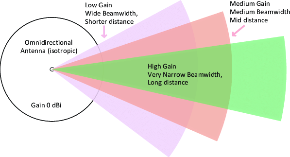
On 5/27/2024 at 2:00 AM, Jayakumaran S said:sir i want to improve the omnidirectional antenna at 340MHz with gain of 25-30dBi, is it possible?
OMNIdirectional and high gain are MUTUALLY EXCLUSIVE can not have BOTH...at 340 mhz omni Vertical colineal VEEERY LOOONG could get you 15 dbi...using several meters of wire...
 2 people like this
 -
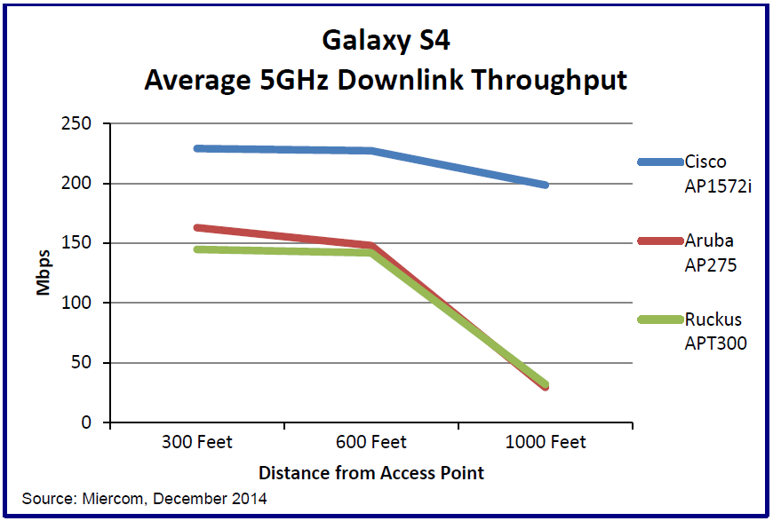
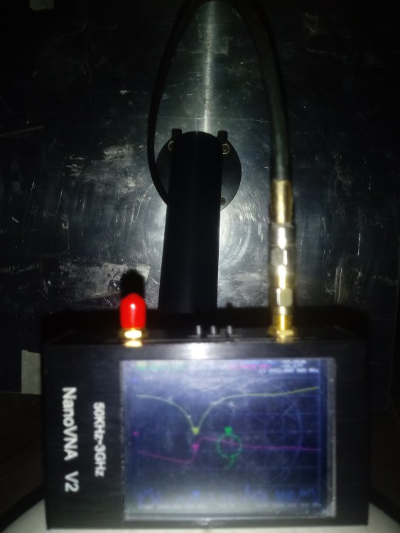
it would be GREAT to put a VNA there on ALL 5 and check HOW they behave ...tho
-
4 hours ago, Rtyon said:would you recommend the best wireless adapter with high power and sensitivity for long range coverage and thanks in advance
what standard (speed) and frequencies ?...2.4 5.8 A B G N ...AC
2.4ghz b/g/n High sensitivity (- 96 dbm at 1mbps) anything with AR9271 (Tplink tl-wn 722n Version 1) 150 mbps max
-
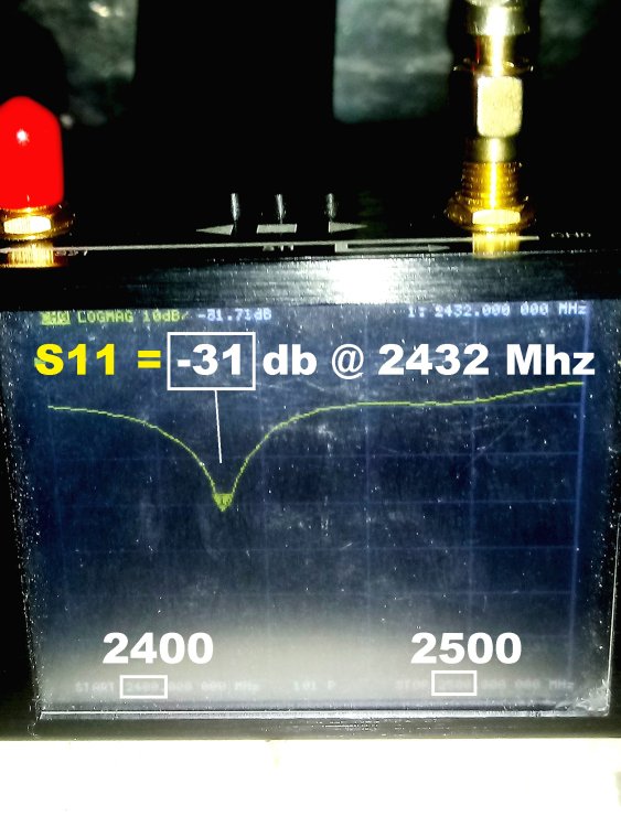
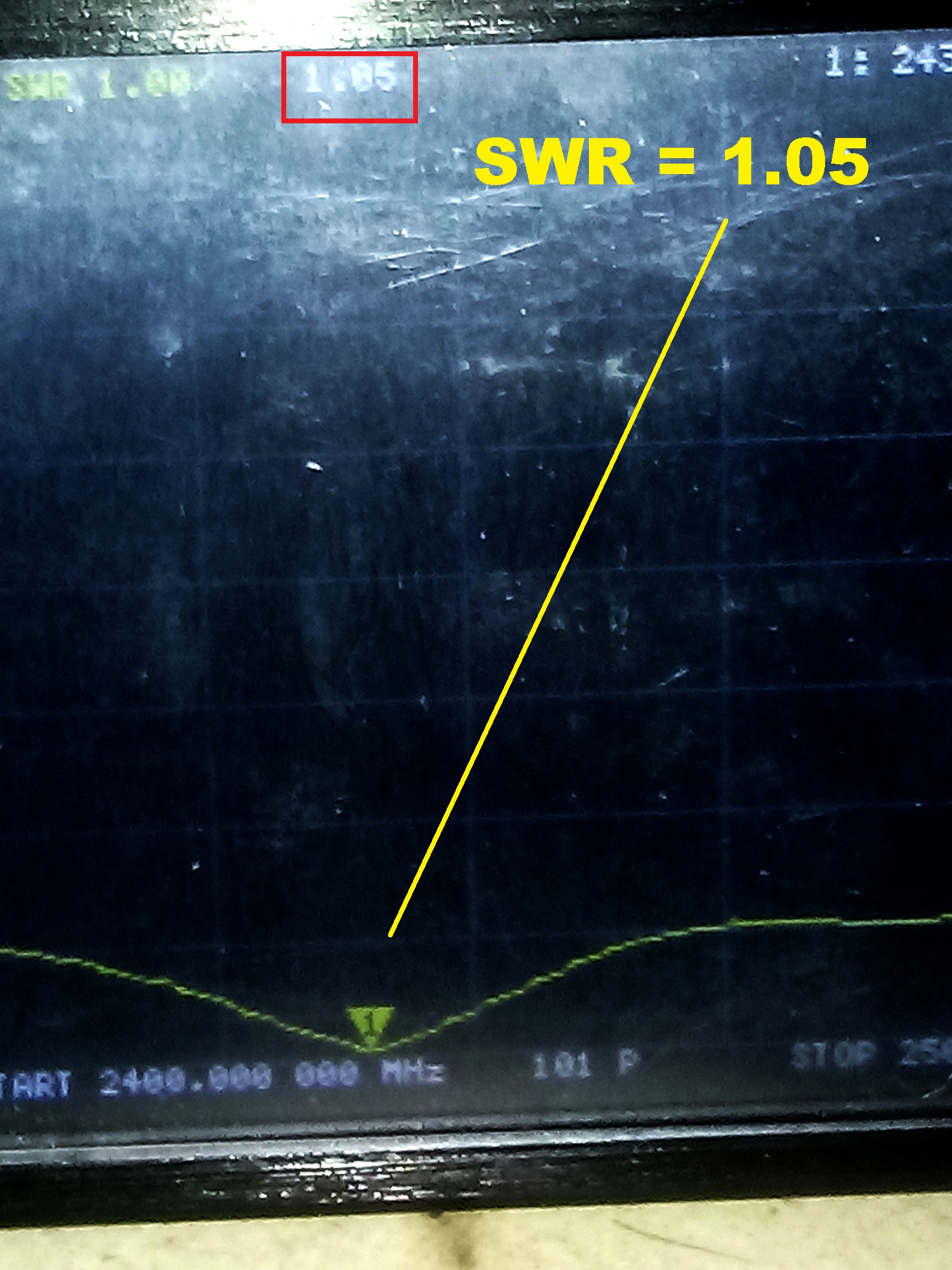
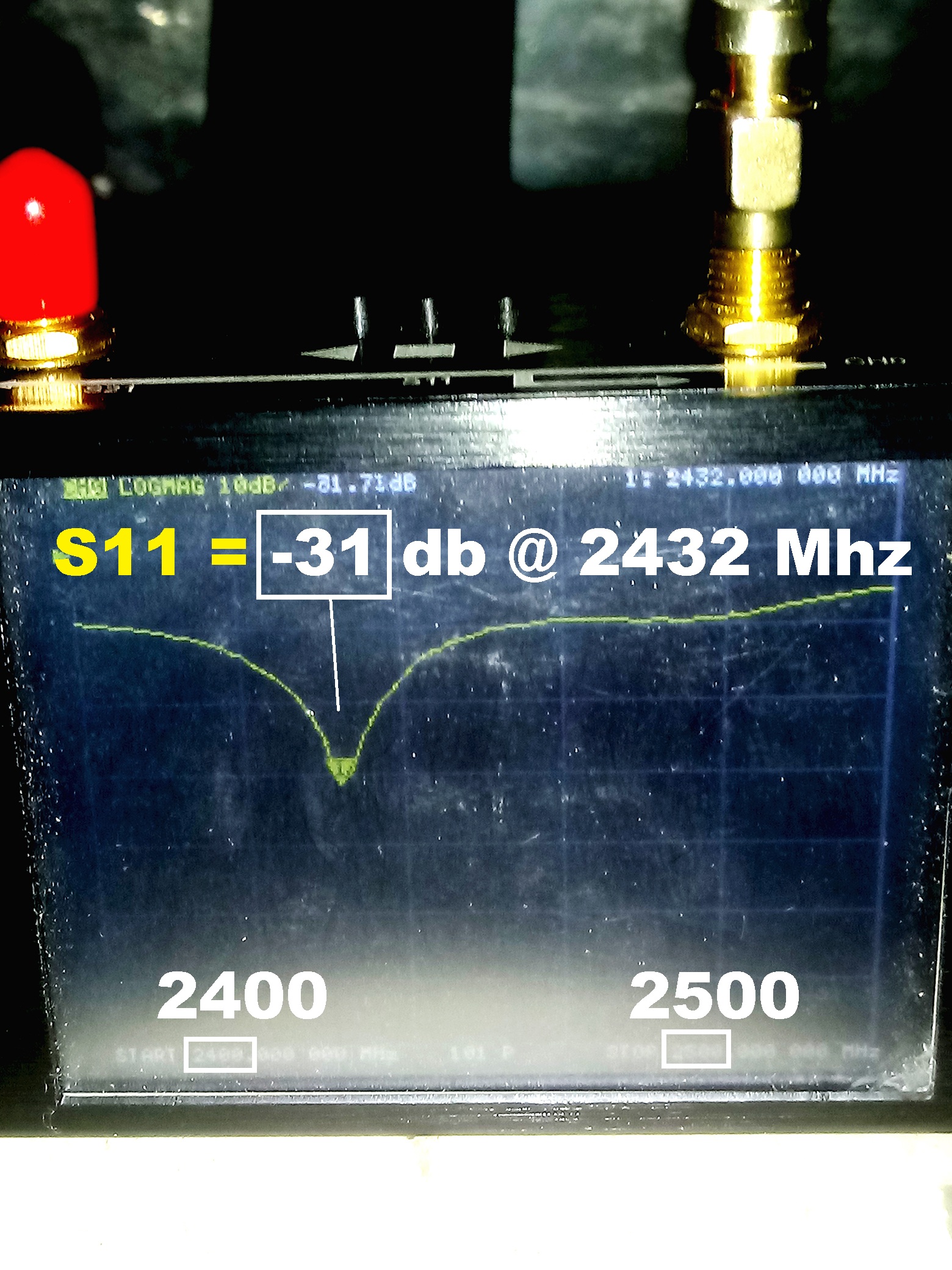
VNA measurements

 1 person likes this
 -
FR4 have lots of disadvantages (efficiency at RX lost , losses at TX a lot ! , never know the Tangent loss and dielectric constant for each material , fr wouldn't be on POINT ever ) you'll need an antenna analyzer or vna to be on frequency PS: only "advantage" size is smaller than metal on air
1 person likes this -
-
yeah , it's easy with the model....pretty sure you are gonna end close to 1 meter by 60 cm or more GRILL...
-
On 24/2/2024 at 4:03 PM, Edel2020 said:It really looks simple....what design to do to get closer to 20db at about 20 km in band 3 1800 MHz?
Wire grill
(big 80 cms at least) OR parabolic dish EVEN BIGGER 1.2 1.5 meters
 1 person likes this
 -
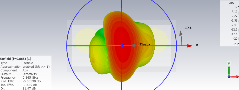
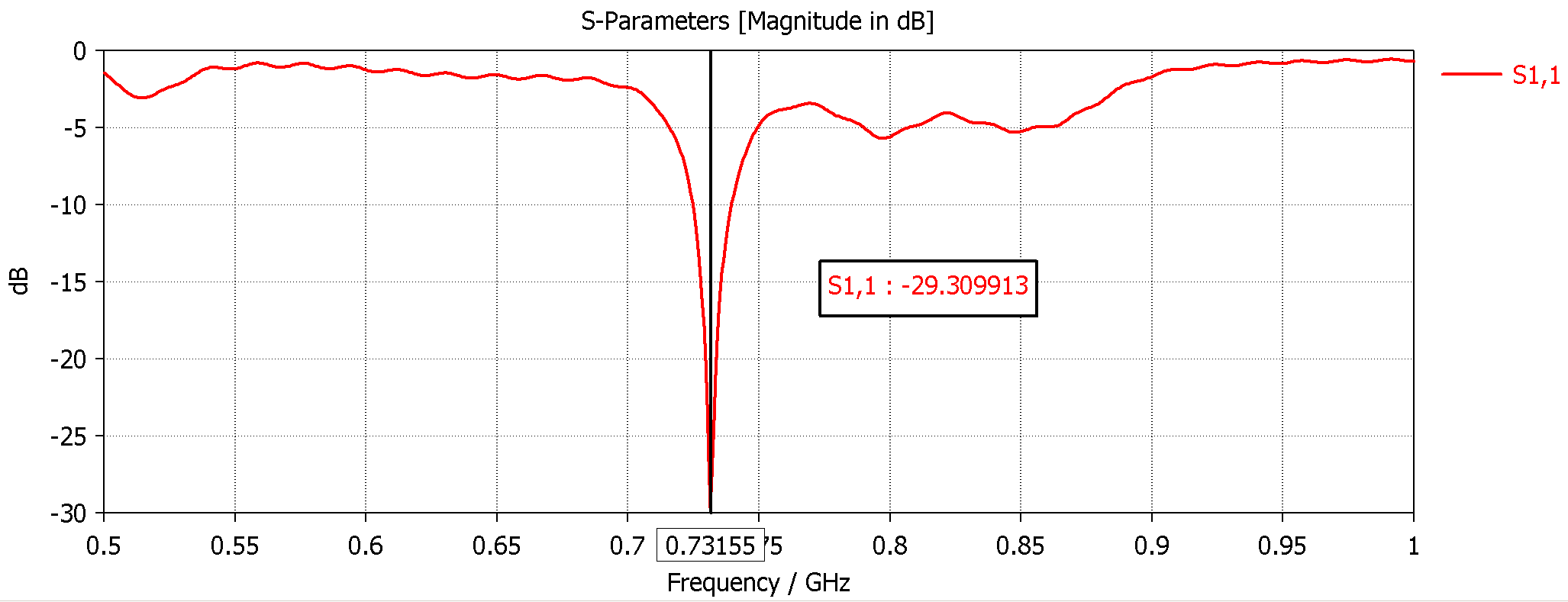
Easier ,for me, if YOU choose ANY 2-3 patches design (10dbi) ( need a frontal picture)
and then we'll make it work at 725mhz...
1 person likes this -
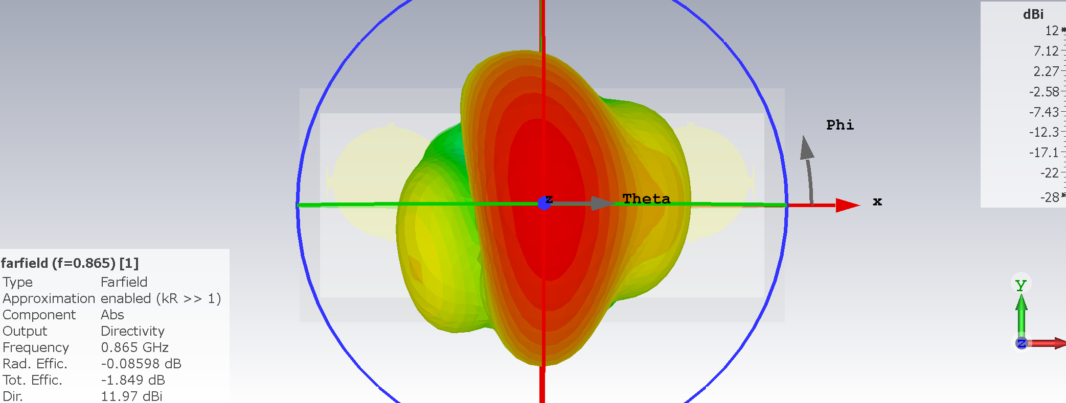
Easily 12 dbi at 725 mhz
-
-
Could be made to ANY frequency , Circular pol (could be made lineal easy) efficiency could be better NOT using FR...

-
On 23/12/2023 at 9:00 PM, eco32 said:{,,,this construction is a bit wrong, mcNeill doesn't really do good things...!!!}
McNeil, He performs titanic antsy work in making phantoms, but do not fully understand it, for example, phase shifters are called load coil, and so on and so on...
{,,,on this forum there is such a dipole in the correct construction...!!!!}
HAMs do not know it, I have not yet seen any HAMs construction with the use of this type of matcher/balun. Most popular is this one:
This is material for a separate topic, LTE/Wifi antennas rarely have a balun.
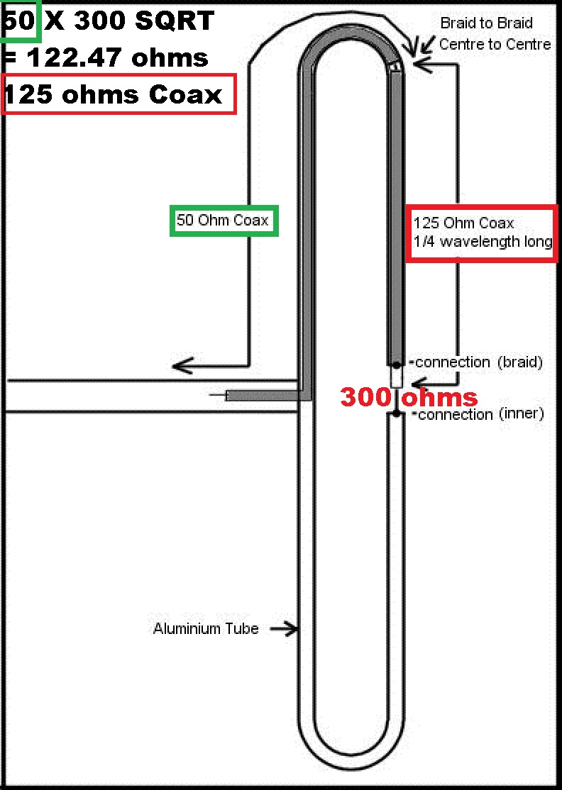
4:1 balun (50 ohms to 200 ohms , 75 ohm to 300 ohms , etc)
2 people like this -
Correct adaptation from 50 ohms to 300 ohms antenna (Quarter wave long should take velocity factor of Coax in length ) 0.66 PET , etc

-
On 4/12/2023 at 4:43 PM, Edel2020 said:How much loss will the published model have?
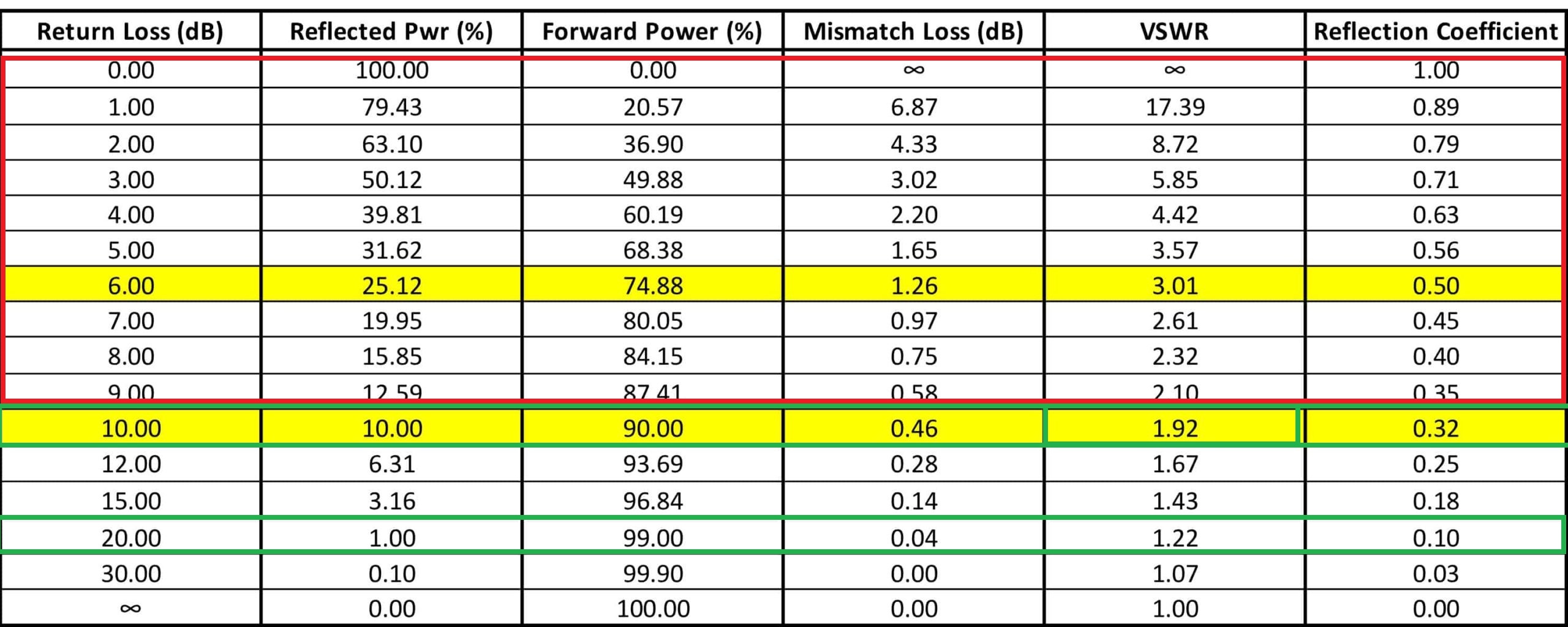
a Ratio between antenna Impedance and radio impedance the bigger the difference bigger the losses...let's sat 300 ohm antena/ 75 ohm radio 4:1 VSWR = close to 40% reflected power on TX...on RX it's gonna be WORSE...(small signal)

-
On 17/11/2022 at 10:05 AM, vova.gumerov said:Hello Jomy! I hope everything is fine with you. And we have a disaster ....... To make such antennas, you need a 3D cutter! Such things are not done with scissors and a grinder!
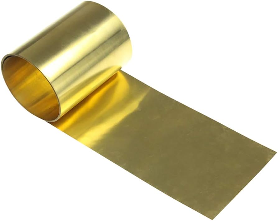
0.2 0.3 BRASS paper...? and a sharp cutter...several tries (using a printed PAPER taped on top) cut through the printed lines...?
solder the vertical strips...
PS: 0.2 is pretty RIGID...
-
Yagis hit a WALL at 15 dbi most of the times (with 15 elements and a BIG reflector)...you need 2 for 18 dbi , 4 for 21 , etc


in Modeling antennas
Posted
that error is related to SOLVER choice and MESH size...(either reduce mesh size or try TLM solver Time domain)