Register now to gain access to all of our features. Once registered and logged in, you will be able to contribute to this site by submitting your own content or replying to existing content. You'll be able to customize your profile, receive reputation points as a reward for submitting content, while also communicating with other members via your own private inbox, plus much more! This message will be removed once you have signed in.


Admin
Administrators-
Content count
4446 -
Joined
-
Last visited
Posts posted by Admin
-
-
-
1 person likes this -
-
,,,okay,take it...
,,,but to build an antenna in CST, you should also see this topic...
-
,,,some drawings if possible...!!!
-
,, like how to mount a RP-SMA connector ...
-
,,,firstly, I think you have to learn to use CST...!!!!
-
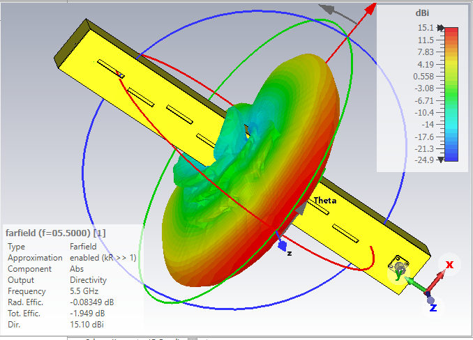
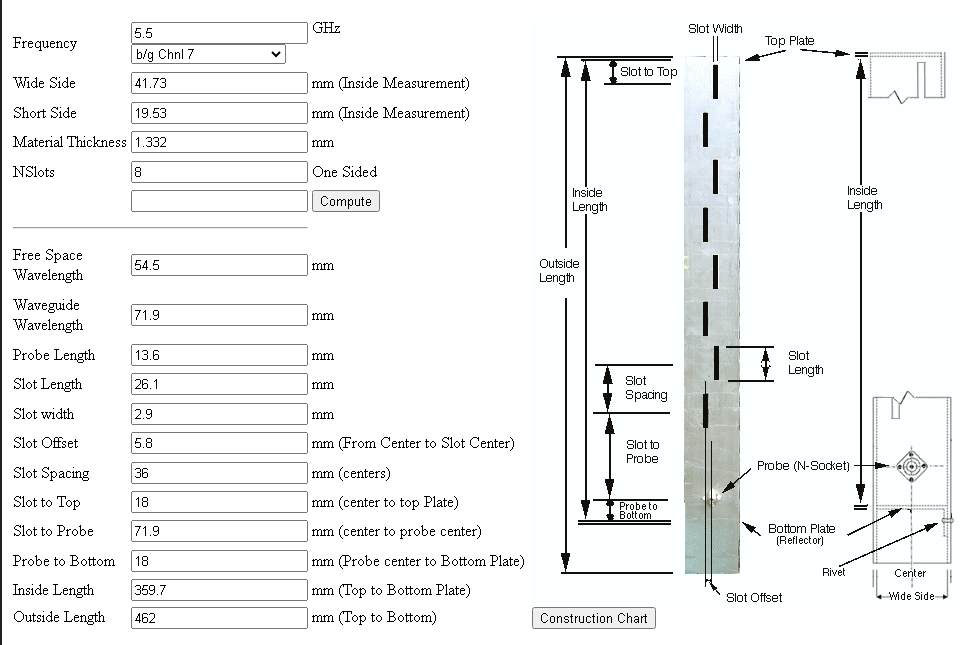
Waveguide slot antennas are a type of microwave antenna that use a hollow metal tube, called a waveguide, to transmit and receive electromagnetic waves. They have slots cut along the length of the waveguide, which act as radiating elements. Waveguide slot antennas have some advantages over other types of antennas, such as high efficiency, low loss, and wide bandwidth.
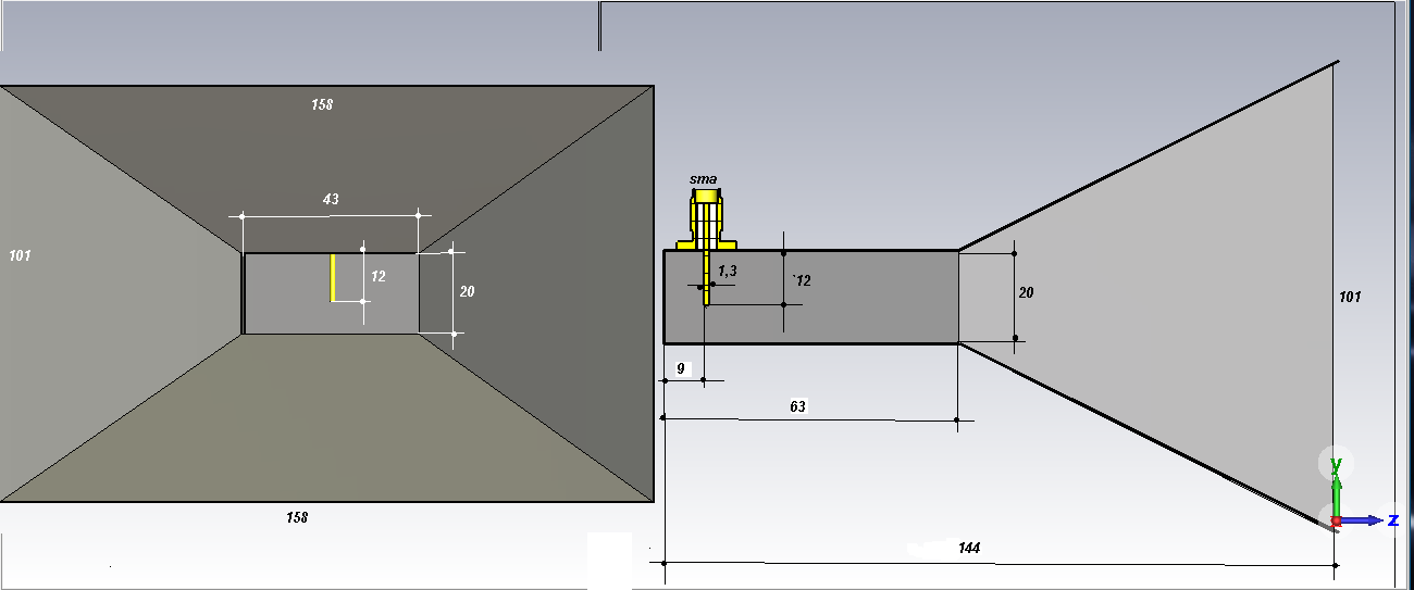
Single Sided 8 Slots Waweguide...41x20x360mm....
 1 person likes this
 -
3 people like this -
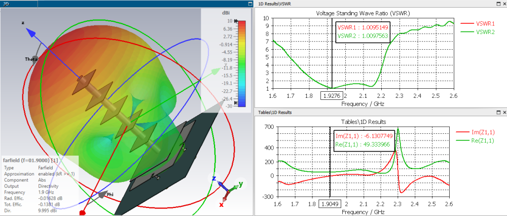
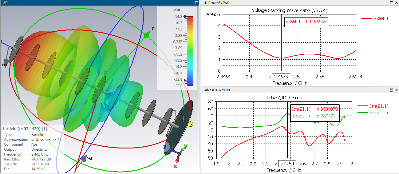
A new design of circularly polarized (CP) patch-helix hybrid antenna with small ground is presented. The proposed antenna consists of a driven patch, a parasitic patch, and a helix connected with the parasitic patch. The hybrid antenna has a relatively small ground, making the overall antenna compact. The proposed antenna can be packaged in a thin cylinder and can be easily mounted in the space-limited systems. Good impedance matching was achieved by capacitive coupling between the driven patch and the parasitic patch, while high gain was obtained with a small ground due to relatively uniform current along the helix.
 4 people like this
 -
,,,yes, I received this drawing from Egor on VK...
,,,and yet, this antenna is not very good...
-
,,,I know, I posted on VK, I want the dimensions...!!!
1 person likes this -
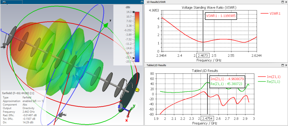
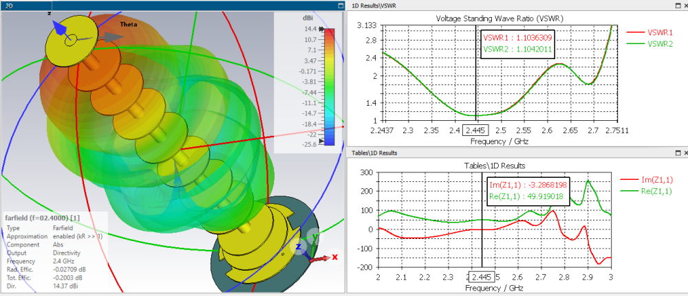
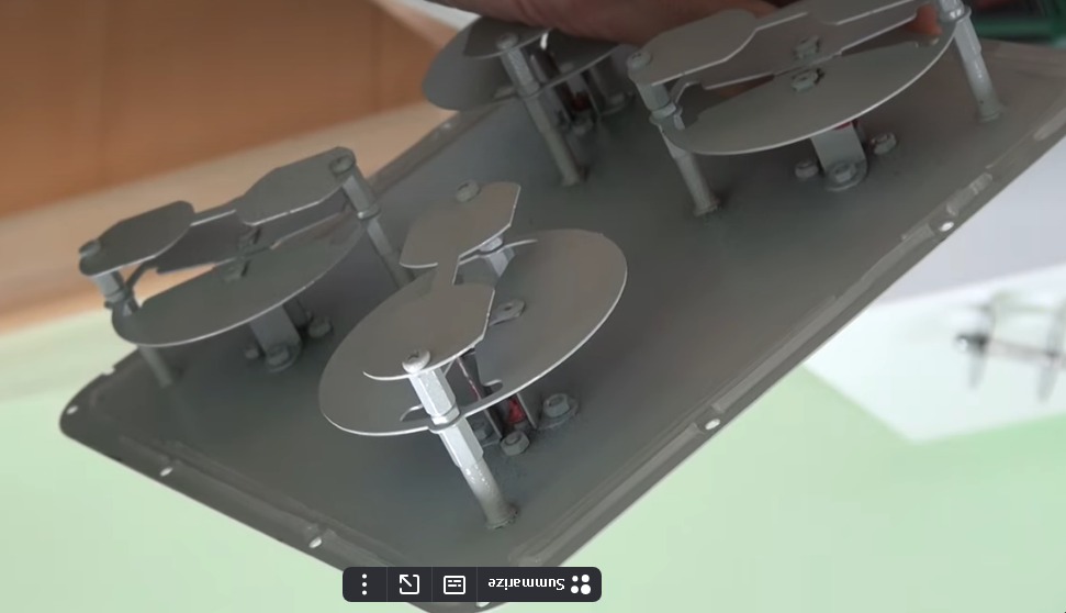
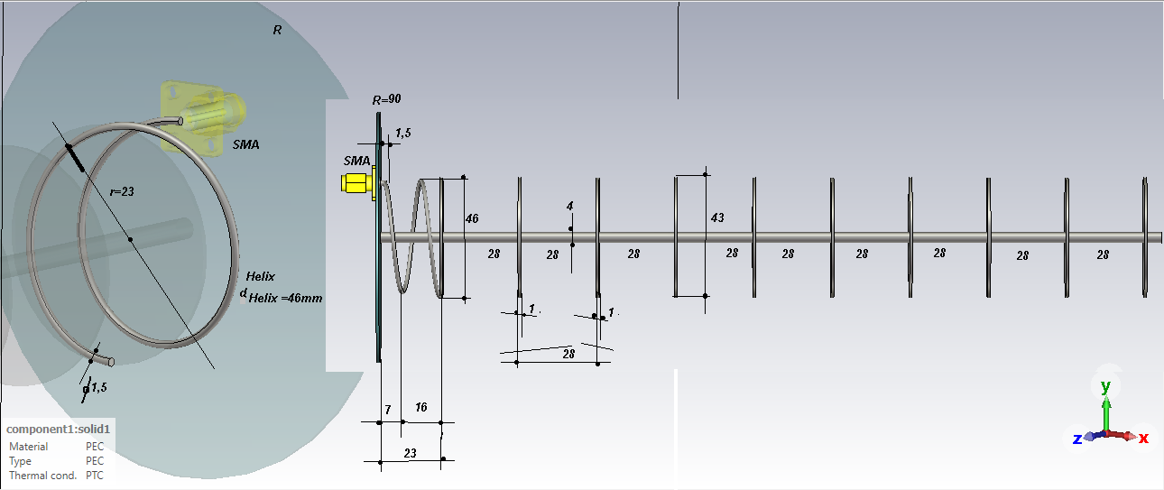
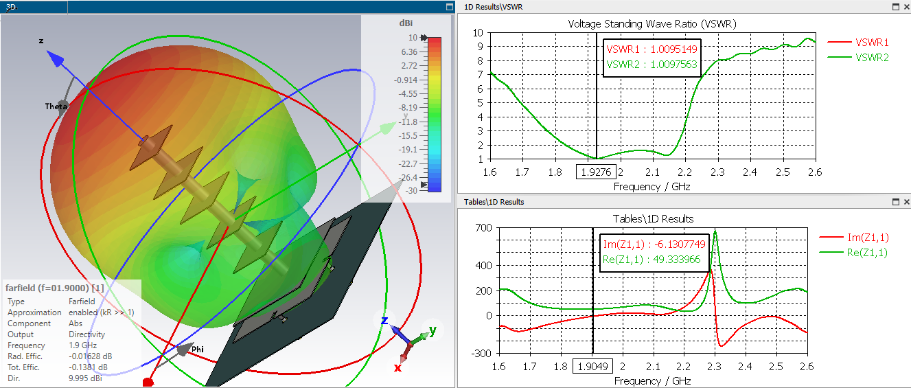
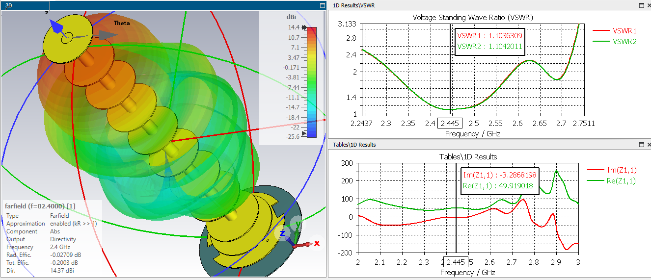
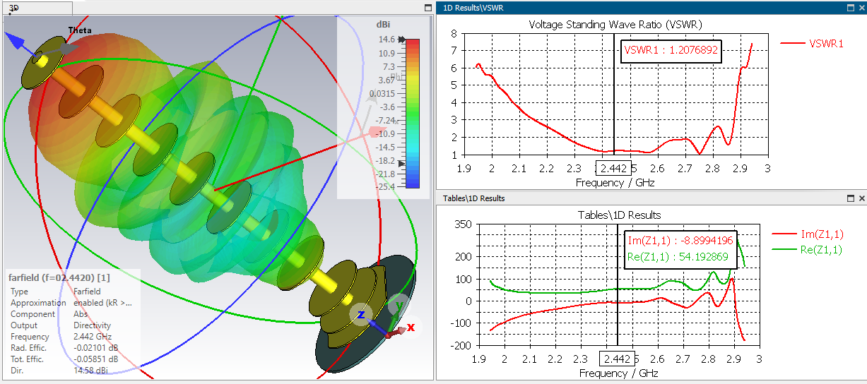
,,,after a certain number of disks(15), their number no longer matters, because the gain of the antenna increases insignificantly...!!!
-
Clanon, how do you make this practical antenna, isn't it a bit complicated...???
1 person likes this -
,,,it is also possible with slots in the active disk ....!!!
-
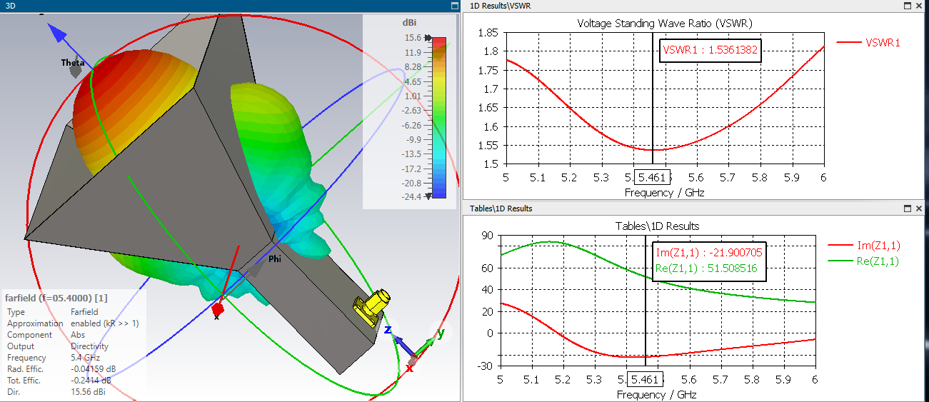
Electrical characteristics
Operating frequency range, MHz 2500-2700
Native gain, dBi 9-10
Resulting gain and beam pattern width level -3dB for different diameters
offset parabolic antenna(at 2600 MHz)
0.55 m 21dBi 13 gr.
0,6 m 22dBi 12 gr.
0.9 m 25dBi 8 gr.
1.3 m 29dBi 6 gr.
1.5 m 30dBi 5 gr.
Bottom width in the H-plane by level-10dB, deg 110÷120
Bottom width in E-plane level-10dB, deg 90÷96
Decoupling between antenna inputs, at least dB 28
Input impedance, Ohms 75
SWR in the operating frequency range, max. 1,5
Permissible power, W 10
Polarisation vertical+horizontal
Mechanical characteristics
Weight, g 380
Overall dimensions, m 0, 145 x0, 145 x0, 145
Connectors 2 x F-female
Emitter Material galvanized steel, brass
Protective coating powdered polymer paint
Material of the protective box Polycarbonate
-
,,,certain users requested this and I have to comply...!!!
1 person likes this -
Of course !!!
-
75 ohm cable (for TV only), not for wireless(modem,antennas,etc) use...!!!
-
1 person likes this -
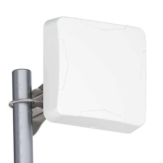
Petra-10 MIMO 4x4-Universal compact panel antenna for 4G / 5G modems and routers that support MIMO 4x4 technology. F=1700-5000MHz, CU=7-12dBi, connectors 4 x N-female, X-pol, decoupling between channels of more than 20dB.
The PETRA-10 MIMO 4x4 panel antenna is designed for use in a set of equipment for 4G (B1, B3, B7, B38, B40) and 5G (N77, N79, N78) wireless data transmission systems at frequencies of 1700-5000 MHz.
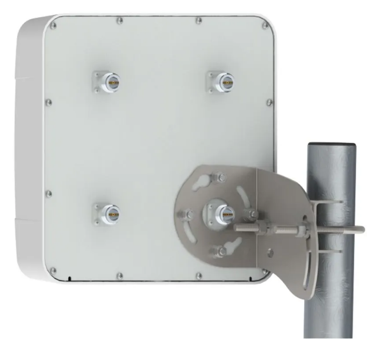
This antenna is compatible with MIMO 4x4 equipment, as it has four connectors for connecting to the equipment. You can also connect two modems with MIMO 2x2 technology to the antenna for redundancy/summation of communication channels.
Advantages of the PETRA-10 MIMO 4x4 antenna :The wide band of the antenna allows you to work in all current and future fastest cellular communication bands
Full support for MIMO 4x4 technology.
Active emitters are reliably protected from precipitation by a housing made of UV-resistant plastic and have an extended service life
The antenna inputs are short-circuited by direct current between the external and internal conductors, which reduces the probability of static electricity accumulation at the modem input and makes the use of a lightning arrester optional (with a small length of the connecting feeder between the modem and the antenna).
Electrical characteristics
Operating frequency range, MHz 1700÷5000
Gain factor, dBi 7.0÷11.5
Bottom width in the H-plane, deg 47÷73
Bottom width in the E-plane, deg 46÷72
Side lobe level, max -12 dB
Decoupling between ports in the operating range, not less than 23 dB
Input impedance, Ohms 50
SWR in the operating frequency range at the inputs, max. 1.8
Permissible power, W 10
Slope of polarization of received / emitted waves -45°/+45°(X-pol) or 0° / 90°(V/H)
Mechanical characteristics
Antenna weight, g 1185
Mounting on a pipe with a diameter of, mm 30-52
Operating temperature range -60°C to +80°C
Overall dimensions without mounting, m 0, 2x0, 2x0, 08
Permissible wind speed, m / sec 25
Connectors 4 x N-fe male
Material of the protective cover- Polycarbonate
Antenna and mount material -Steel, Galvanized steel, Brass
-
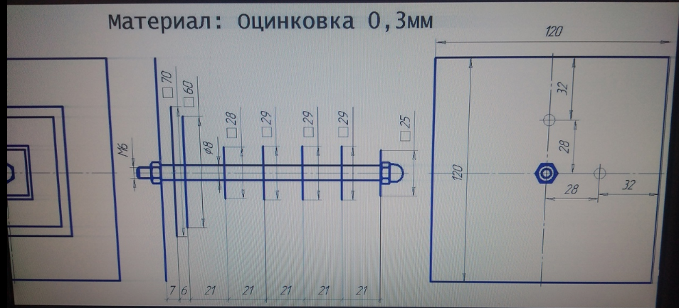
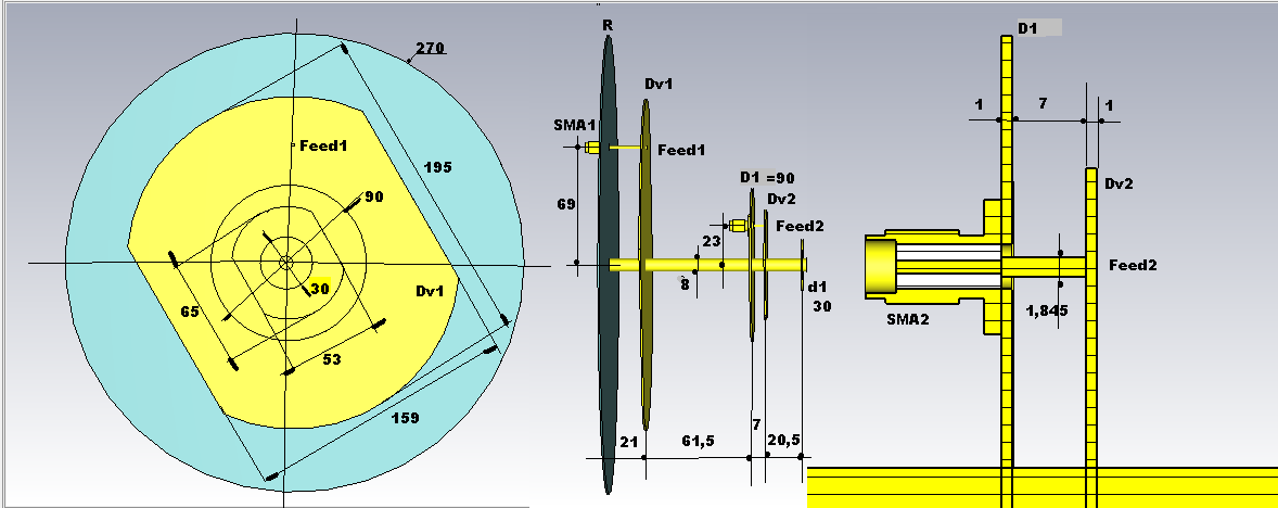
,,,a Bester antenna with other dimensions...
,,,and the practical realization of Egor- Free Wardriving...
-
-
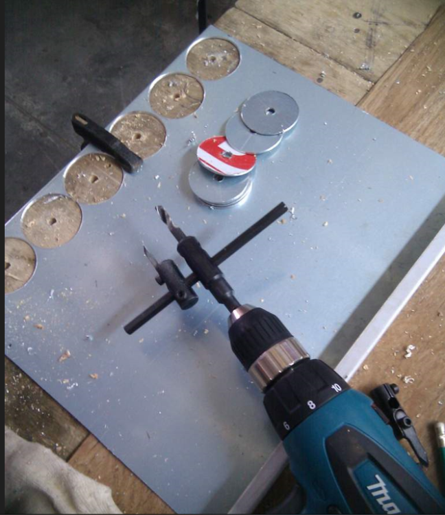
Method of cutting rounds...
 1 person likes this


in Antennas for 2.4 GHz band
Posted
Bester by Pylypenko...