Register now to gain access to all of our features. Once registered and logged in, you will be able to contribute to this site by submitting your own content or replying to existing content. You'll be able to customize your profile, receive reputation points as a reward for submitting content, while also communicating with other members via your own private inbox, plus much more! This message will be removed once you have signed in.


Admin
Administrators-
Content count
5054 -
Joined
-
Last visited
Posts posted by Admin
-
-
,,,and a video....
3 people like this -
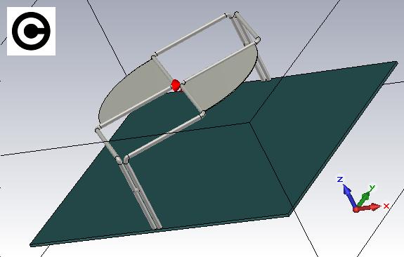
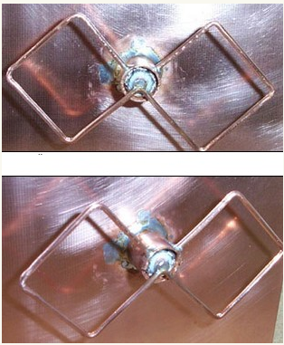
I think it should look like this, but it need to make a 250 Ohm adaptation...
 1 person likes this
 -
okay buddy, I'm glad that you work with the CST...!!!
Please, post your results, here in the forum...!!!
-
On 4/18/2018 at 9:06 PM, TomCat said:Hi admin,can i use this on 5200 Mhz frakens?
,,,no,
if you want for the 5.2 GHz frequency ,tell me...?!
-
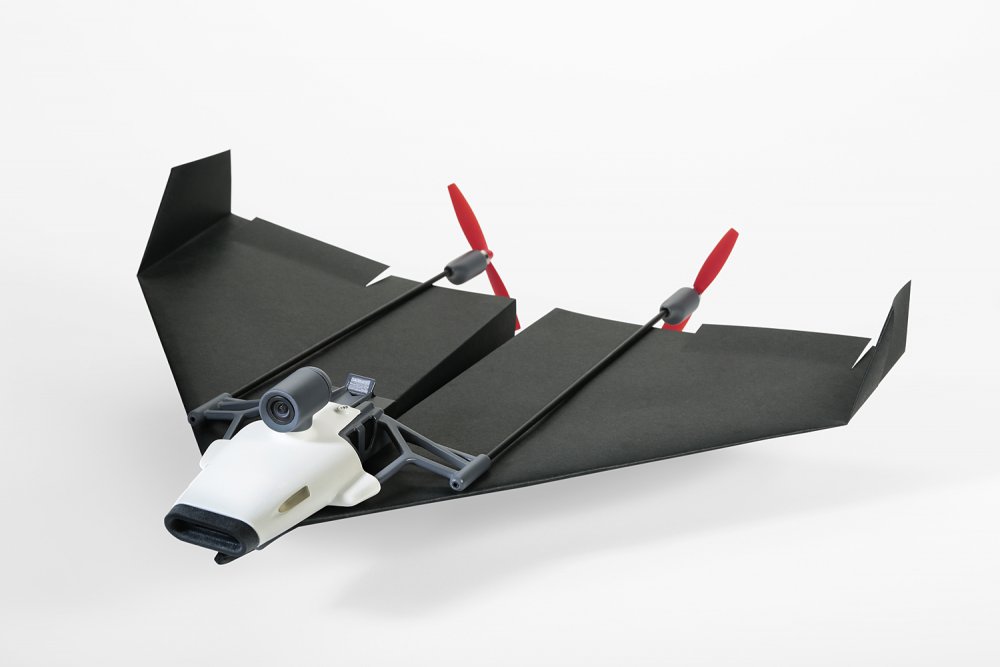
,,this it"s for 3DHS/EF 95" Electric Only Extra 330-E....https://www.rcgroups.com/forums/showthread.php?2963732-3DHS-EF-95-Electric-Only-Extra-330-E
1 person likes this -
,,,,from Garry ...
-
Garry, what do you think of that...???
-
On 4/19/2018 at 7:33 AM, Lonely Angel said:Hello. It turned out to optimize antenna?
,,,not yet, but the end is near...!!!!
-
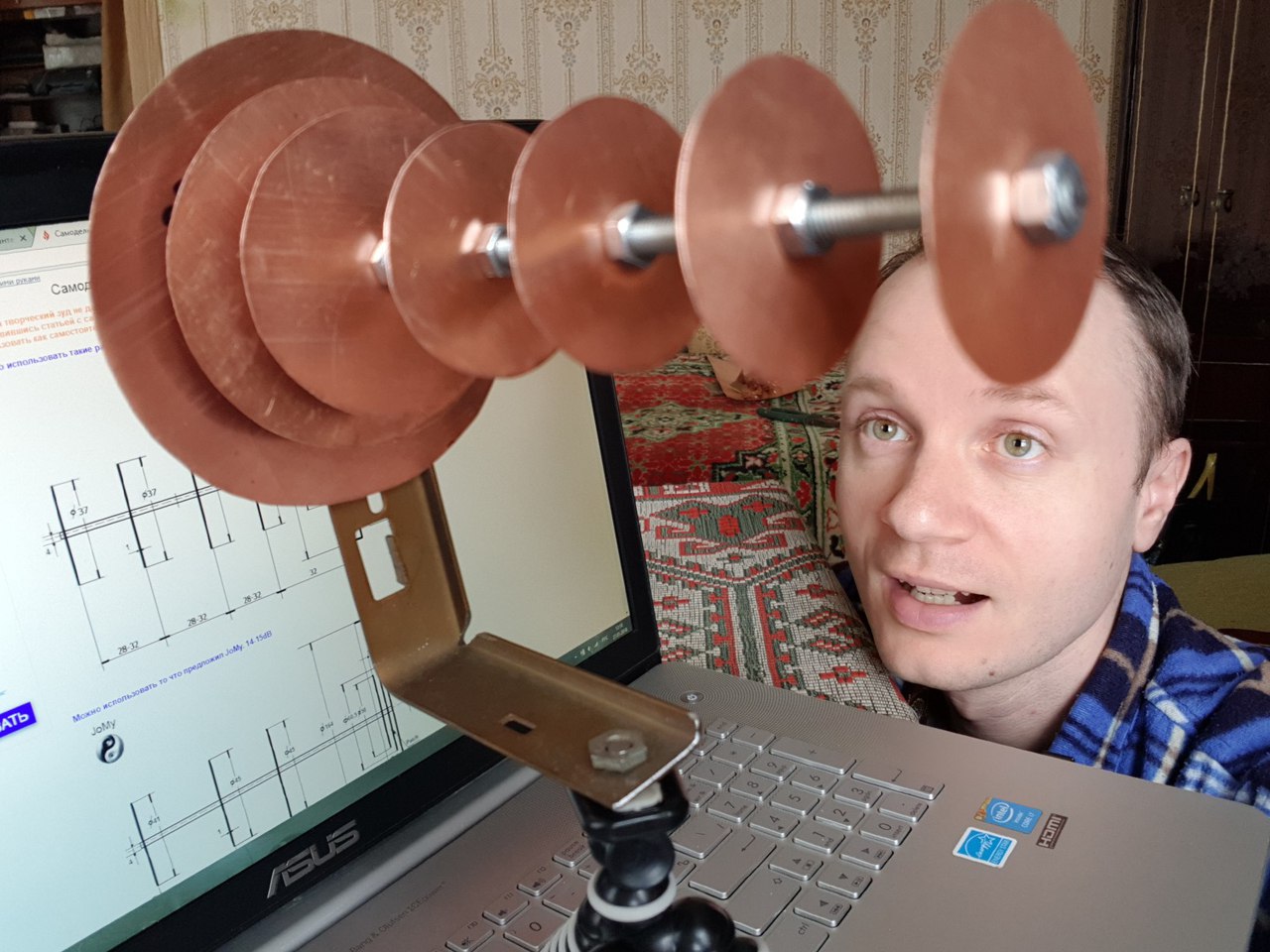
,,,from center to center coils...
0,025*lambda = tape
-
...the minimum distance between coils = 0,62*lambda ( wavelength )
....the bestt distance between coils = 0,8-0,9*lambda ( wavelength )
-
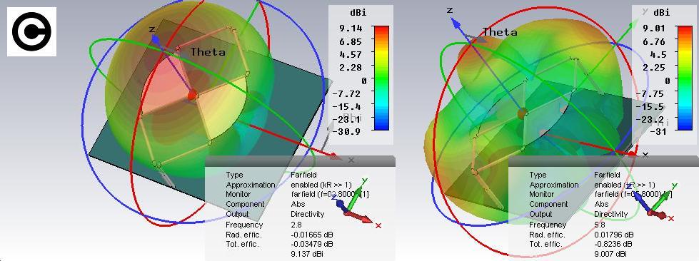
Hi buddy,
I like your achievement, but you must to know that the gain of a cp cross biquad is negative, that is it is less than a single dipole because of the power split to feed two antenna elements from the same source,by cross-polarization, you lose about 6 dBi.
Okay , I tried this solution without the results being spoken on the internet
,,,try this option too...
-
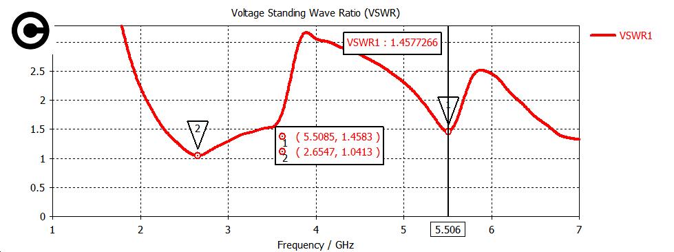
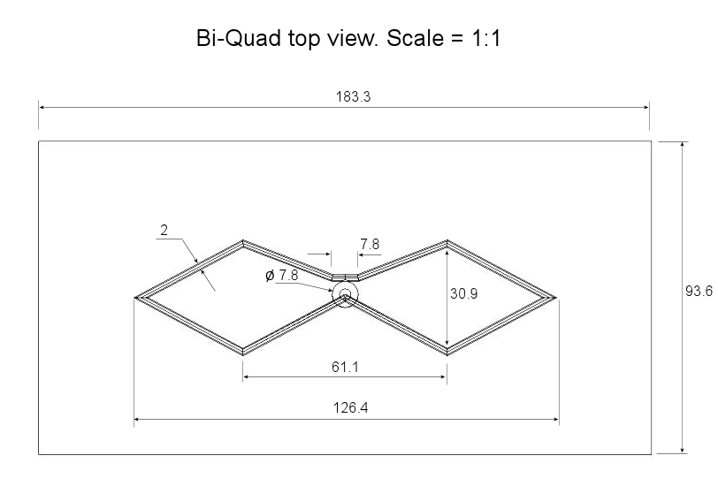
With this biquad form, you can get a bandwidth increase...
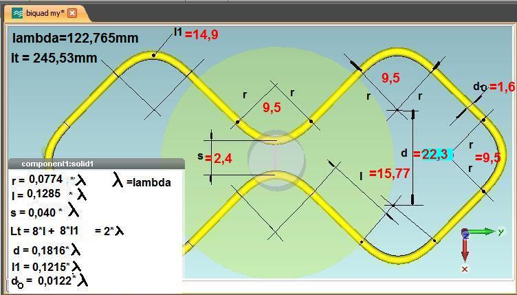
Dimensions are given on the axis of symmetry of the Cu Wire
 1 person likes this
 -
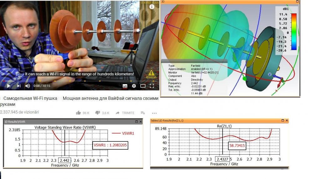
From here,,,http://give-all.biz/articles/samdel/samodelnaya-antenna-analog-obluchatelya-bester...,KREOSAN copied....!!!!!
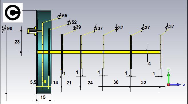
These are my drawings...!!!!
 1 person likes this
 -
Yes, but not with this patch geometry...!!!
-
4 people like this -
-
Rob, please, if you can, post YouTube video by Andrew Mc Neil and the sizes of your antenna!!
1 person likes this -
Okay, that's better...
"you do not watch all the forum...!!
4 people like this -
ok, from where did you get this helix geometry...??
-
,,,hi buddy...!!!
"impressive, did you make these helix antennas ...?
-
,,,hy dude..!!!
I do not know, simulation is long time ago ...!!!
-
-
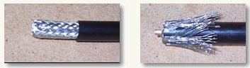
Ok, it does not matter the type of coaxial cable, but the inside diameter of the pipe must can be pressed on the coaxial cable
-
"Yes, here's a solution...
.png.0dfea40f5c0a325876bc58db087124ef.png) 2 people like this
2 people like this

in Antennas 5GHz band
Posted
Compact sector antenna WiFi Ubiquiti airMax Sector 5G 17-90 designed for installation where the placement of a full-sized devices is not possible or desirable. This WiFi antenna is almost twice shorter than the "large" Sector airMax and weighs just over 1 kg.
Despite its modest dimensions, the device has retained all the key characteristics of the family of these WiFi antennas. Ubiquiti airMax Sector 5G 17-90 has the gain of 17 dBi and a wide sweep of 90°. WiFi antenna mounts to wall or post by means of special fastenings.