Register now to gain access to all of our features. Once registered and logged in, you will be able to contribute to this site by submitting your own content or replying to existing content. You'll be able to customize your profile, receive reputation points as a reward for submitting content, while also communicating with other members via your own private inbox, plus much more! This message will be removed once you have signed in.

efeksk
Members-
Content count
121 -
Joined
-
Last visited
Posts posted by efeksk
-
-
On 1/2/2017 at 2:23 PM, Admin said: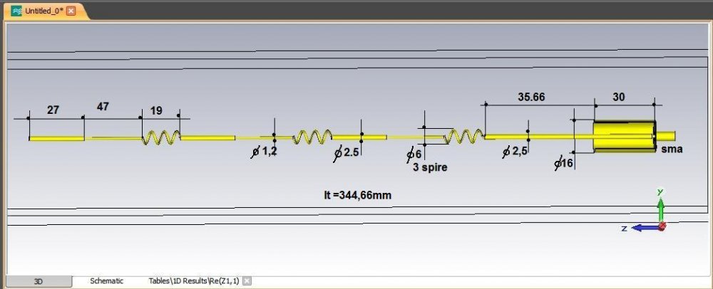
What should the dimensions be for 868mhz?
-
I will produce one for you. And I will share all the measurements with you
-
Yes. But I don't know the actual gain of the antenna. And I don't have any technical data.
-
-
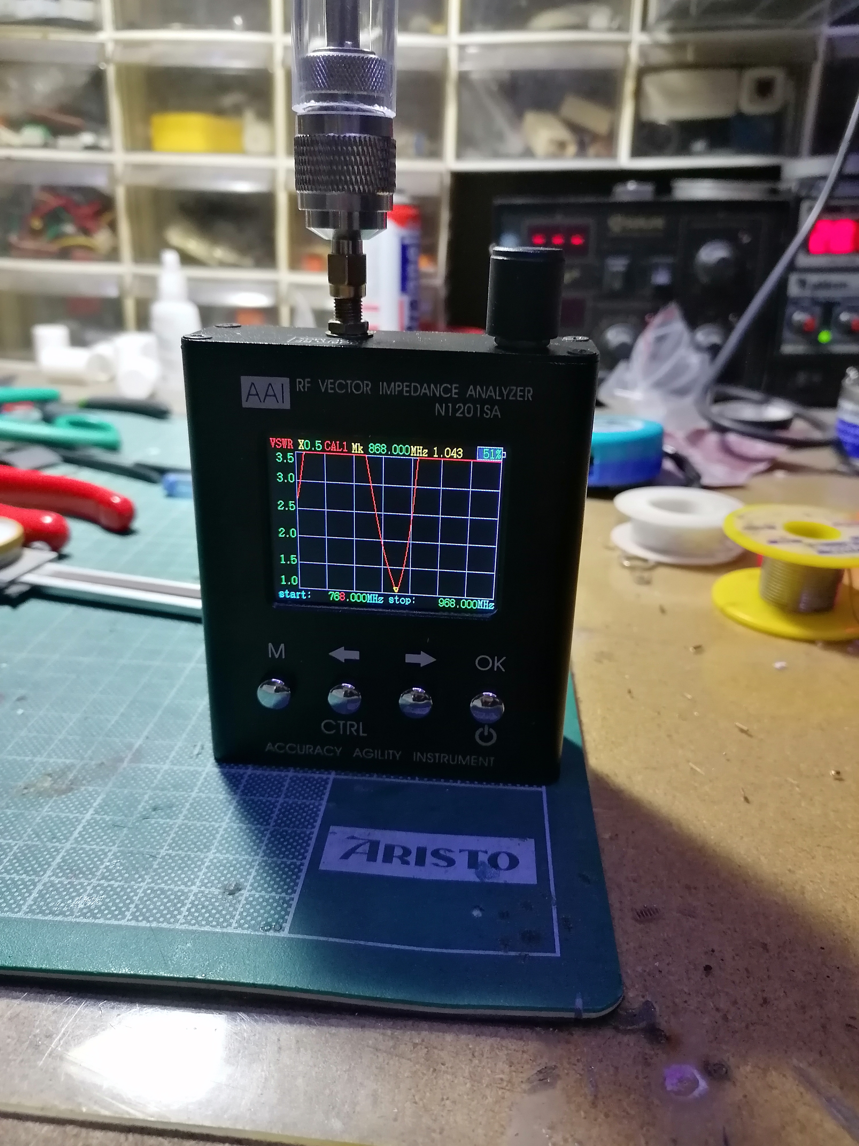
swr value is quite high. There are two ways to reduce this. The first is to move the feed point up or down. The second is to shorten it from the top wire.
-
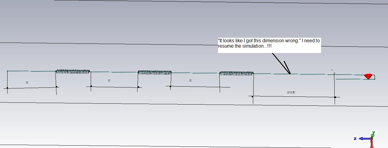
Just now, Admin said:,, bu benim için bir tasarım hatası... !!!
aaa. okay okay. I get it now.
-
10 minutes ago, Admin said:
What did you misunderstand?
-
Understood.
I also installed cst studio.
I want to learn a little. -
I need to be able to run this antenna at 868 mhz.
But it must be highly profitable.
6 dbi
8 dbi
12 dbi
How can I achieve these gains with 868 mhz? -
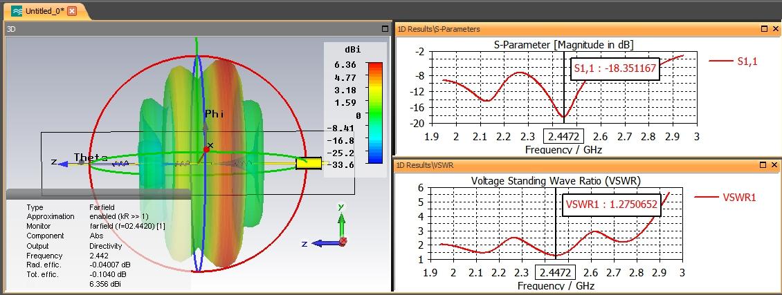
Wow.
You did a great job.
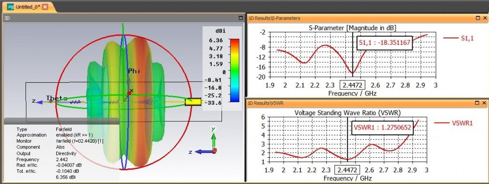
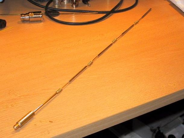
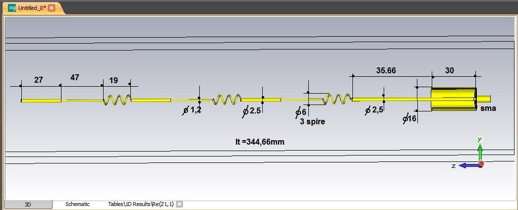
does this test consist of 3 coils?
So how is the test result with a single coil? -
I know the dimensions.
The data in the cst simulation that I'm curious about")
-
Just now, Admin said:,,, ve J Pole anteninin hangi frekanslarda çalışmasını istiyorsunuz ..? /
868 MHz my brother
1 person likes this -
Bu programı kullanmayı öğrenmem gerekiyor.
Nereden başlamalıyım?
I need to learn to use this program.
Where should I start?
-
Hello again, old friend.
I hope I can be active all the time.
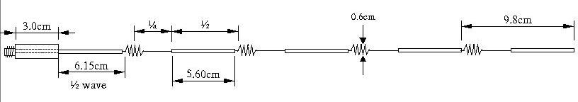
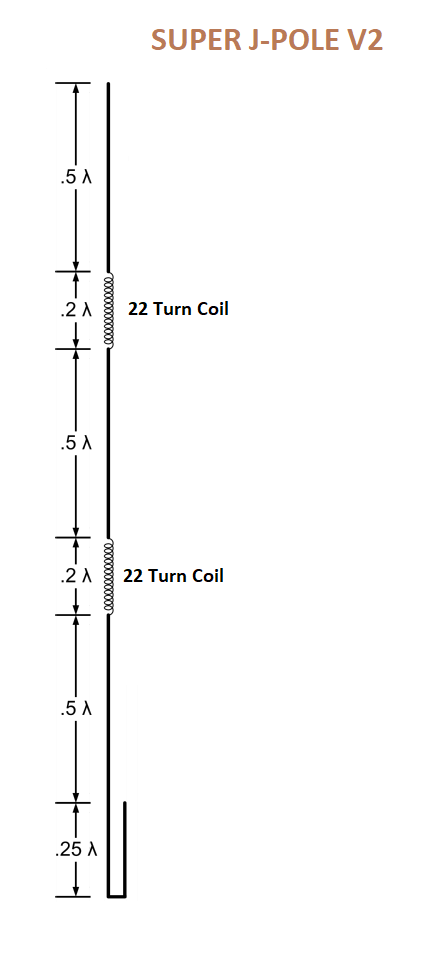
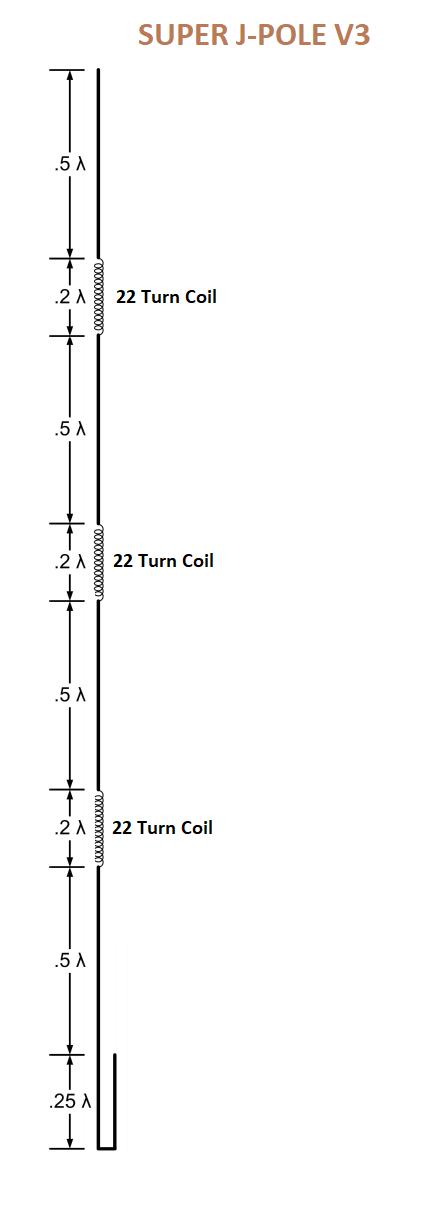
The diameter of the wire used in the antenna is 1.2mm
Coil inner diameter: 3mm
Coil with 22 turns1 person likes this -
Hello my friends.
I hope everything is okay.
I hope you are healthy.
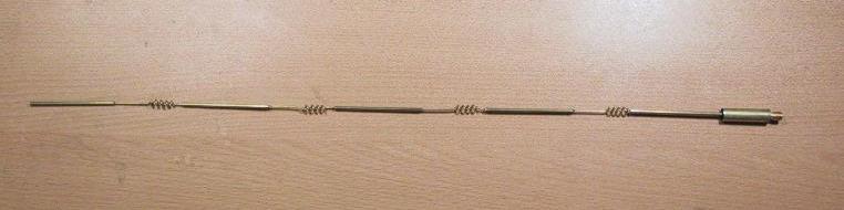
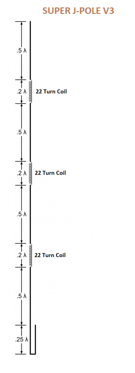
I haven't been able to access the forum for a long time due to health reasons.I'm currently stuck with a j-pole design.
Can we simulate this antenna according to the attached pictures?
What will be the technical values of 3 different versions such as pattern, gain, swr?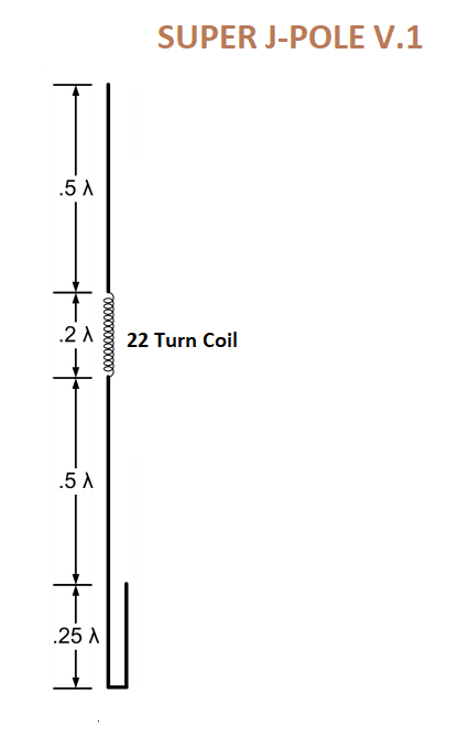

-
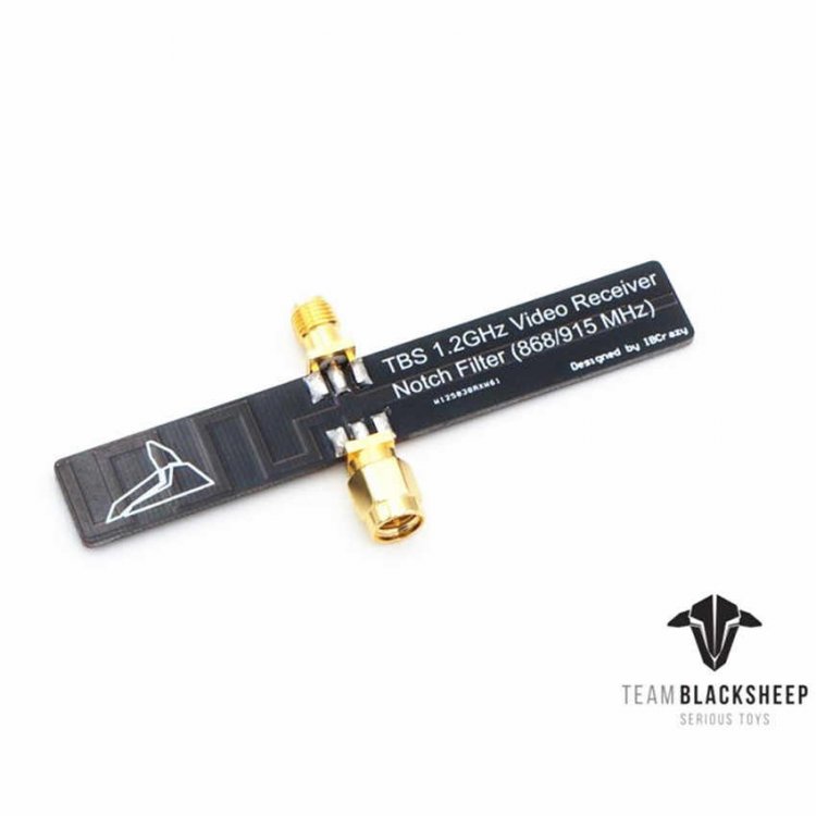
It's been a long time. I was not active due to health problems. Now I'm slowly coming back. I have added a notch filter in the attached picture. This filter is produced so that the two RF systems working side by side do not interfere with each other. 1 watt rf transmitter in the 915 mhz band and 1200 mhz rf video receiver are used to avoid interference. This filter is to protect 1200mhz rf video receiver from noise from 915mhz rf transmitter. If this filter is not used, noise appears in the image. Should I do to build a pcb filter like this?
 1 person likes this
 -
with 1.2 ghz
-
It looks great.
2420 MHz and 5775 MHz.
I can think of it as a metal with a laser.
If you can give me the relevant files I can cut with metal laser cutting.Please tell me what materials I need to use
-
ooowww. yessssss
-
It must be pretty good. And the size should be max 12x12 cm
-
But it's pretty big
-
This is a great man
-
-
What would you recommend for 2.4GHz

in Modeling antennas
Posted
What should the dimensions be for 868mhz?