Register now to gain access to all of our features. Once registered and logged in, you will be able to contribute to this site by submitting your own content or replying to existing content. You'll be able to customize your profile, receive reputation points as a reward for submitting content, while also communicating with other members via your own private inbox, plus much more! This message will be removed once you have signed in.

clanon
Members-
Content count
844 -
Joined
-
Last visited
Posts posted by clanon
-
-
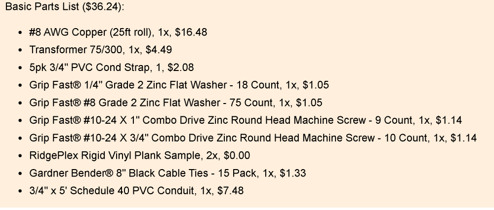
8 AWG = 10 mm2 Copper...
Tube is PVC 3/4
with CLAMPS (shorts)
-
in Meters...?

-
a Mesh wire REFLECTOR would give at least 3 dbi more...and tailor the impedance...down to 75 ohms...MAYBE...
-
On 21/9/2024 at 0:49 AM, Admin said:Clanon,try to update the program....https://en.taiwebs.com/windows/download-cst-studio-suite-10756.html
Already did , didn't like the changes...tried 2 versions , 2021-2022...went BACK...

-
23 hours ago, naumoves said:I've tried to design something like plate sma connector with the same dimensions and materials.
Do you know were i can find pre-built sma connectors for cst with right impedance characteristics?
1 person likes this -
On 21/9/2024 at 9:53 AM, naumoves said:I think i won this challenge
") (with parasitic patches).
(with parasitic patches).
Check efficiency , usually is poor for FR4...(it hurt RX) , if you are close to 90% it's good enough...imho
-
I can't open your cst (i'm using 2020)...
-
same size or smaller and close by...TRY SLOTS on the patchs , that works too
1 person likes this -
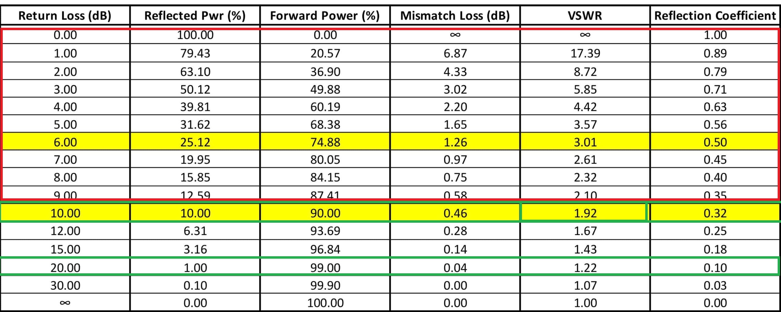
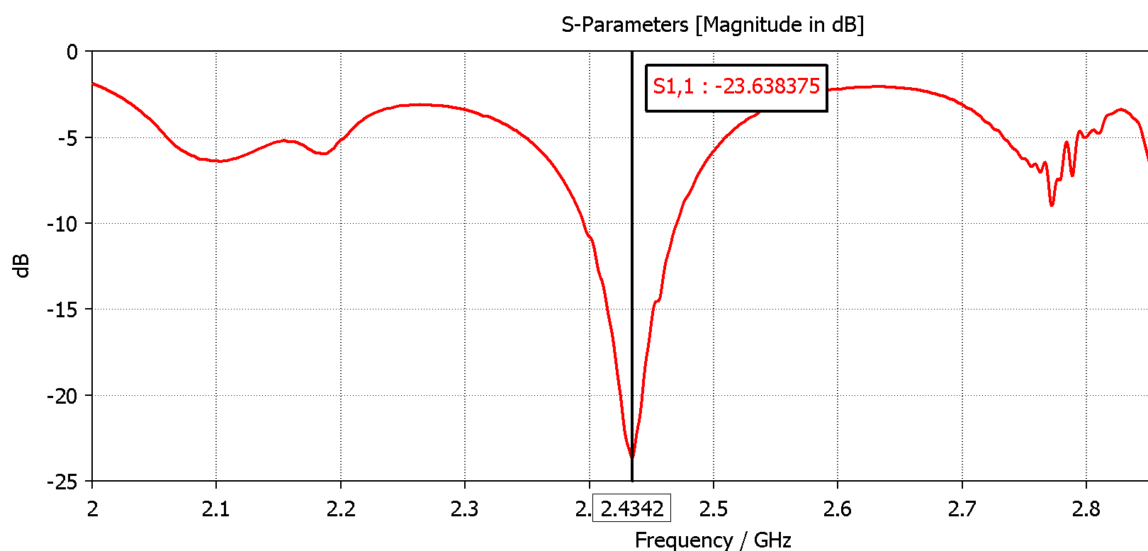
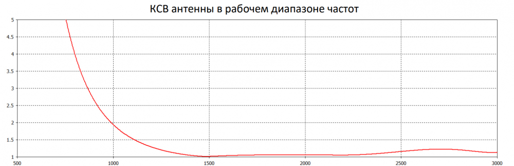
S11 (Return loss) is the energy absorbed or rejected and it relates to VSWR...from -10 to -20 you have under 2 VSWR, a GOOD antenna...and it should go from the lower frequency you need to the highest (bandwidth)
 2 people like this
 -
Adding parasitic patches (close by) would make a new s11 dip (higher or lower than the original) if those TWO dips are close by you'll widen the bandwidth ...(at some s11 expense , s11 goes up , less energy absorbed ) if you stay under -10 and efficiency is good...you are good to go...PS: efficiency is ALWAYS GOOD for me , cause i use STYROFOAM as dielectric...
1 person likes this -
ALL metal is WAY BETTER (no losses or dielectric shifts) , with 4 patches at 3.5 you'll end up close to 15 dbi (if EVERYTHING is ok) band width might end up to narrow...tho
2 people like this -
3.5 ghz (from 3.4 to 3.6 ghz bandwidth) mimo (more than 20db isolation between ports) at least 12-15 dbi gain...imho (gonna have to put the modem with the antenna close by...short cables...) Opening and soldering NEW cables (low losses) would be better...
-
On 8/6/2024 at 7:37 AM, zetka said:Has anybody tried to measure the real made antenna samples upon those design on some VNA (NanoVNA) and compare the simulations to the real results?
on this ALL METAL structures (if no mistakes have been made) results should be close to simulations(5% 7%) BUT if DIELECTRICS have been used...THINGS GO HAYWIRE FAST and BAD...in MY experience (change in dielectric constant from 1.1 to 1.075 HUGE dimensions and results difference at 2.4 ghz and PATCH ARRAY)
-
1 person likes this -
 1 person likes this
 -
How does the FEED point looks...? it should be be wider band...
1 person likes this -
On 6/8/2020 at 11:55 AM, marsbar said:If you look at amplifiers, these are placed inside a milled solid aluminium block, there must be a reason for that.
That's the COMPLICATED EXPENSIVE approach...BUT it achieves MODULAR SHIELDING of different sections (LNA , RECEIVERS , Local OSCILLATORS , Power supplies , Filters , Switches etc)
1 person likes this -
Yup , EMI shield (Faraday CAGE) aluminum (copper or brass is better) container without interruptions (heat dissipation should be considered) and GROUNDED to GND
1 person likes this -
-
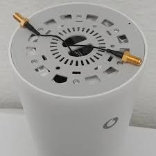
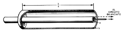
4 hours ago, eco32 said:Thats stubm balun, it may be directed downward or upward, I have no idea what the difference in operation is. Only klow that is to phase shift. (My version in previous page was tunable)
![Base[1].jpg](https://www.wifi-antennas.com/uploads/monthly_2024_08/66cd99d9814a9_Base1.jpg.d032da9984d0c910a31d446e4d45c596.jpg)
Open side pointing up (the direction of the Energy you DON'T want coming through the Shield of Coaxial) imho The confussion comes from the rubber duckie pointing DOWN (open end) cause it is ACTING as a Quarter wave and ground plane to obtain a HALF WAVE dipole...
-
-
-
-

in Antennas for 2.4 GHz band
Posted · Edited by clanon
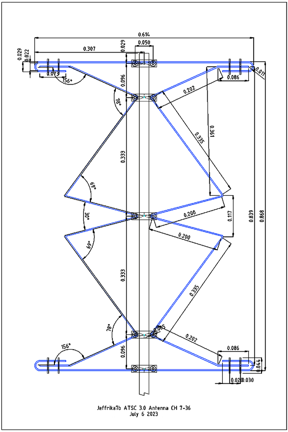
maybe gets better with thick copper wire and SMOOTH rounded Bends...they look to angled ...imho
jeffrika7b.dxf