Register now to gain access to all of our features. Once registered and logged in, you will be able to contribute to this site by submitting your own content or replying to existing content. You'll be able to customize your profile, receive reputation points as a reward for submitting content, while also communicating with other members via your own private inbox, plus much more! This message will be removed once you have signed in.

clanon
Members-
Content count
831 -
Joined
-
Last visited
Posts posted by clanon
-
-
On 8/12/2025 at 9:59 AM, Admin said:WAY MORE REACTIVE than square...
 1 person likes this
 -
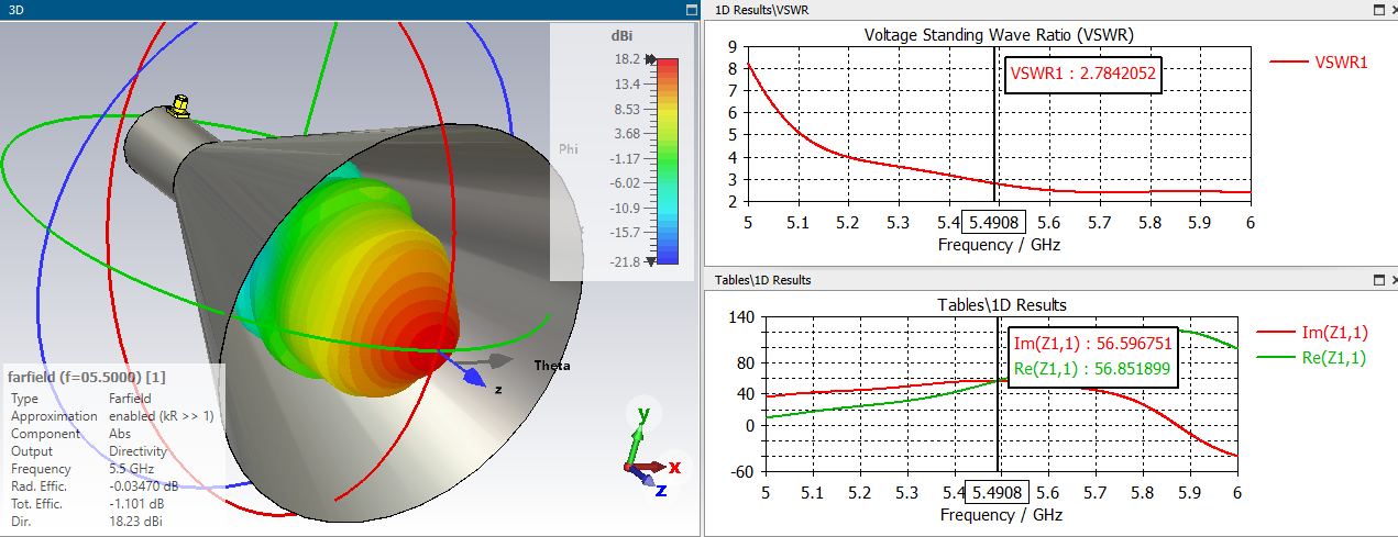
Jomy did you try a conical (cilinder) Horn ?...(should be smoother all around)
PS: the TEM UWB should have a new post...imho
-
I see it done with Brass sheet (rigid no need for dielectric support) OR copper Tape (0,0254 mm) over Polystyrene foam...
1 person likes this -
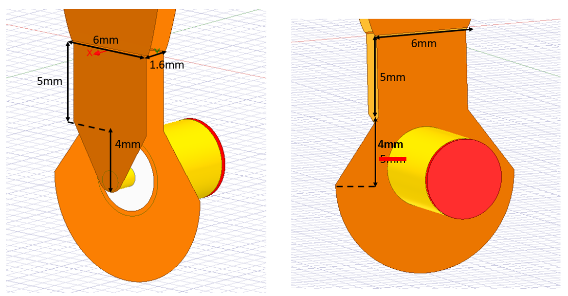
19 hours ago, Docgi said:There is one mistake in dimensions. You can see the rigth one below

is that a BALUN...? looks like it...
1 person likes this -
Nice project (for UWB)...could you post the 3d (.stl .hfss or .aedt) to run it through cst up to 6ghz , and gain seems to go all the WAY to the problematic zone (under 500mhz) nice for an SDR PS: I went with LPDA , cone elemwents...but NOT happy with the results...
1 person likes this -
1 hour ago, Jayakumaran S said:Sir, how can we identify whether an antenna is circularly, vertically, or horizontally polarized? Is there any specific parameter in CST that indicates this polarization type?
1 person likes this -
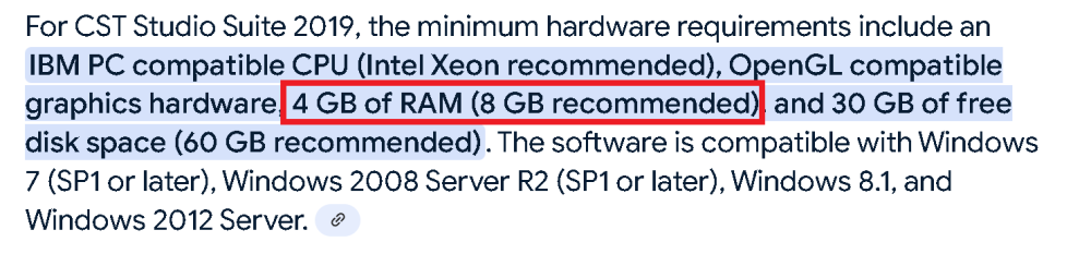
11 hours ago, Jayakumaran S said:Sir, I am planning to purchase a laptop with a budget of INR 50,000. I require it to support CST, HFSS, and other high-end design applications. Kindly share the recommended specifications, so I can choose a suitable model accordingly.
RAM size 8 gb at least (ddr4 better) and Processor cores (8 would be best) are important...(CST mws before 2020 would require less resources) but I used it with 6gb of ram and 2 cores (intel is better) check the GPU acceleration capacity...(heavier than games) used gaming laptop maybe...
 1 person likes this
 -
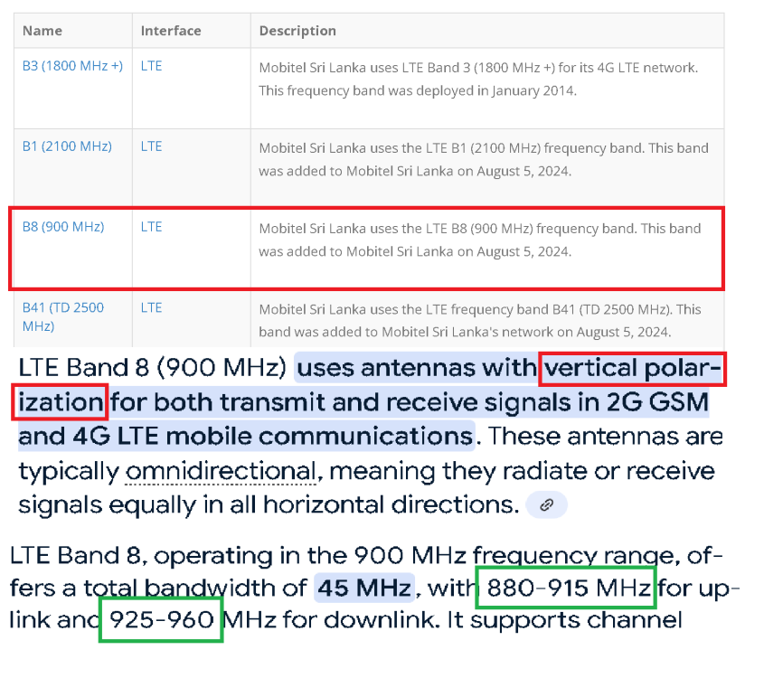
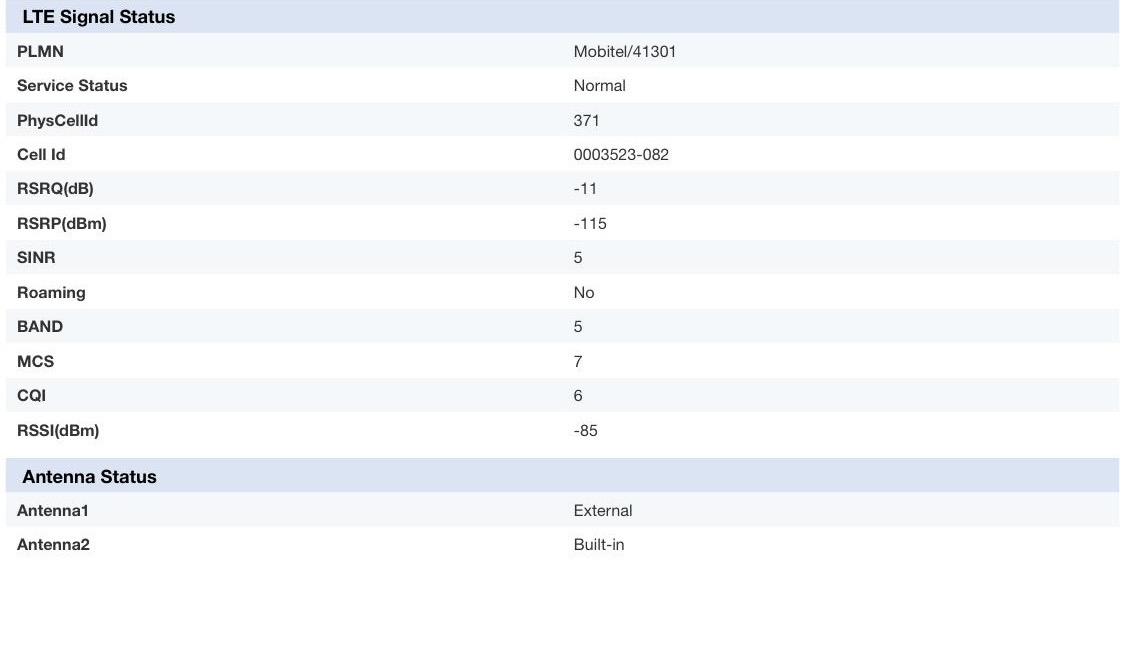
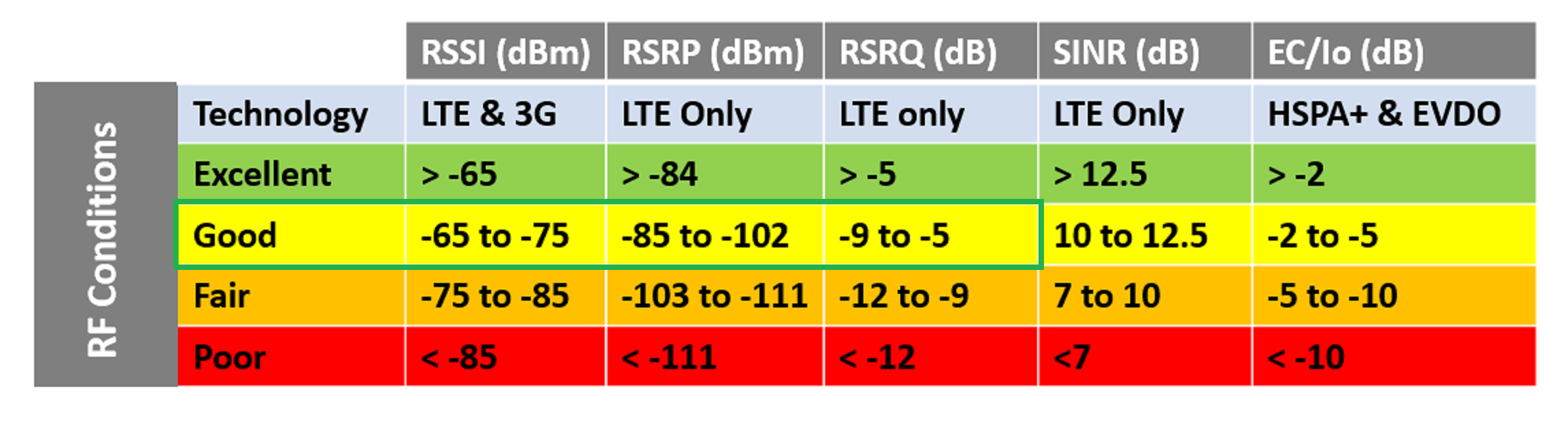
You are using a Circular polarized antenna and tryin to receive a VERTICAL polarized signal...NO GOOD...and shifted band frequency too...
YOUR antenna should provide Vertical polarization and be centered at 920 MHZ with a Bandwidth of 80 MHZ (880-960) Yagi Vertical polarized...
-
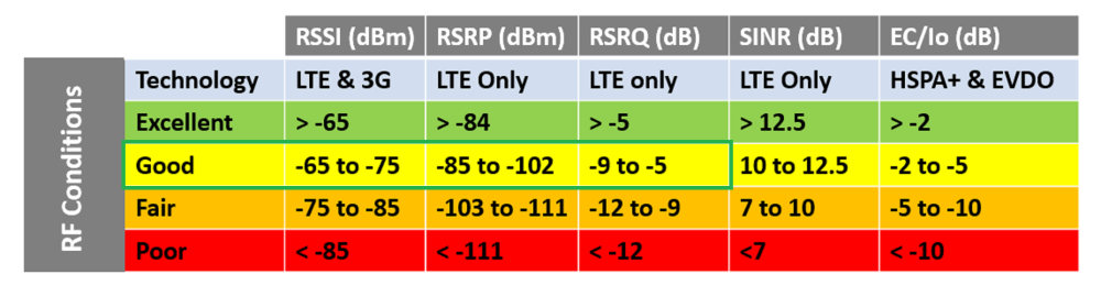
On 7/19/2025 at 9:27 PM, Anjana said:I tried my anttenna and this is the results. My signal tower is 8km far from me. Can you give me another anntenna for bad 5 (850mhz) 15dBi for try
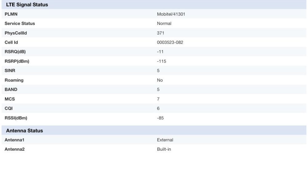
RSSI (signal and Quality (packets received transmited) are too low...you need over 15 dbi at least ...try to make a big reflector (wire mesh , chicken coup wire...at least 1 m , put it in the back of your antenna) Router (waterproof) close by the antenna (losing signal on cables)
-
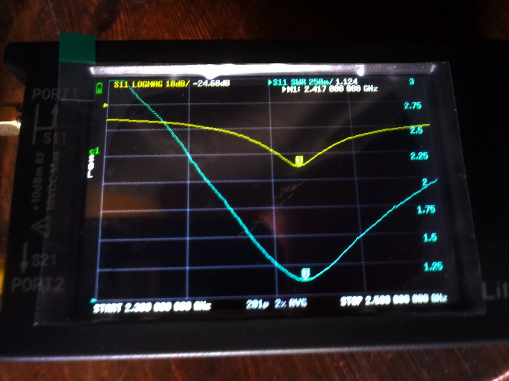
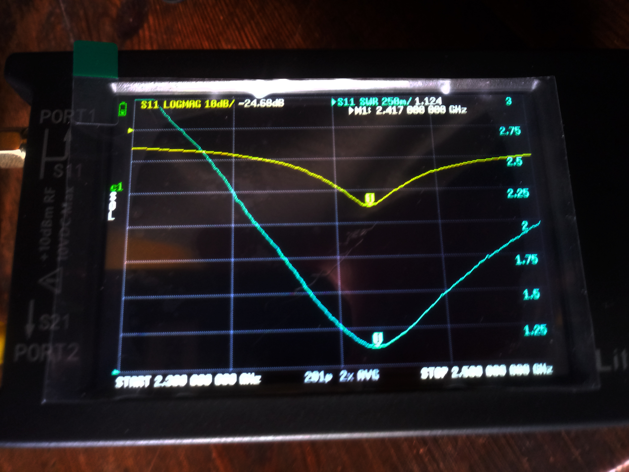
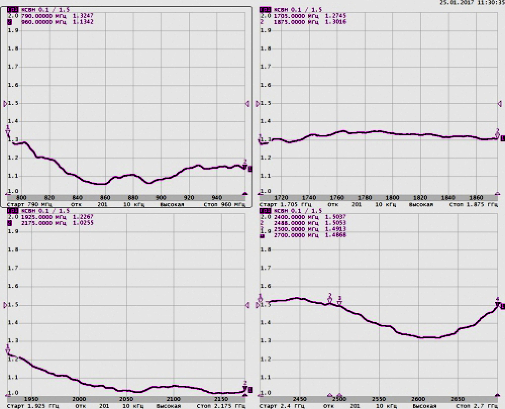
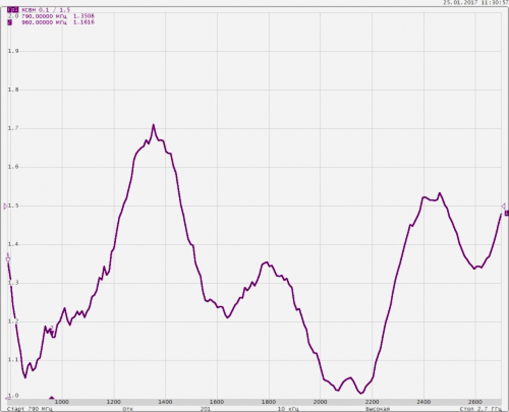
LiteVNA measurements
-
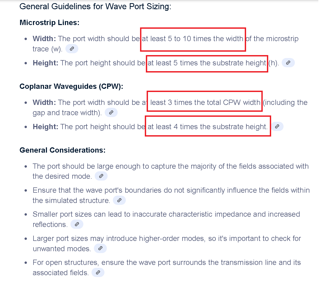
On 7/16/2025 at 10:17 AM, Jayakumaran S said:Sir, may I use the formula provided in CST to determine the size of the wave port in HFSS?
Also, could you please advise on the appropriate height of the radiation box?
 1 person likes this
 -
2 hours ago, Jayakumaran S said:Besides frequency, is there any other reason you choose a discrete port over a lumped port sir?
You use WHAT WORKS (that'll be DISCRETE PORT 1st and WAVE Port at the end) Same for Solver mesh settings
1 person likes this -
3 hours ago, Jayakumaran S said:I noticed the simulation includes a connector. Is it necessary to simulate with one?
Also, if the antenna ends with a copper rod, I have assigned the wave port by selecting the rod’s end face. Similarly, for a copper tube, I selected the tube’s face and assigned the wave port.
Kindly confirm if this method is correct.
Face select inner+pet+shield+outer edge , then assign wave port (ALL of them should be leveled)
puting a PORT on the END of an ANTENNA is a NO-NO
1 person likes this -
18 minutes ago, Jayakumaran S said:could you please send this corrected design file.
And where i can see the OHM stuff in CST.
Still workin on it (good antennas BAD FEED NETWORKS !) I'll upload it if it works give me time
After the simulation is OK on Port impedance Z (should be 50 ohms ) Electronics = Cables= Antennas (50Ohms=50Ohms=50ohms)
-
Those TWO collineal NEED an adapter to SHOW 100 Ohms in the middle (50ohms on coax)
Two identical antennas of 50ohms would give 25ohms in the middle not right
I ran one alone and is promising...

-
Those TWO collineal (2,4ghz) NEED an adapter to SHOW 100 Ohms in the middle (50ohms on coax)
Two identical antennas of 50ohms would give 25ohms in the middle not right
-
First of ALL
BOTH Your Coax cable HAVE NO SHIELD...
Adding a SHIELD present a NEW problem (they would be DANGLING in the AIR -No Connected to ANYTHING)
-
Use THIS is more PRECISE (PS: also try rotating the tube gradually to get the POLARIZATION in the SWEET SPOT) Good work!
1 person likes this -
Yeah , that figures...it should have some impact on Simulation (as Ferrite FeO2)
-
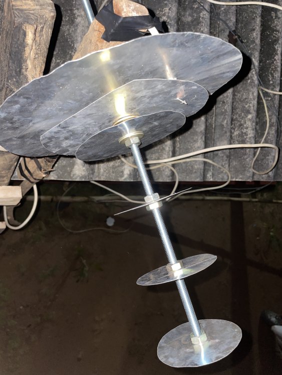
BI CONE , central feed wide band (base is dielectric)
-
BI CONE , central feed wide band (base is dielectric)
-
-
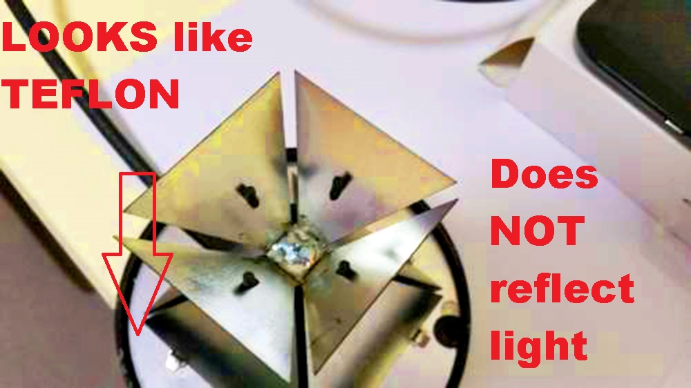
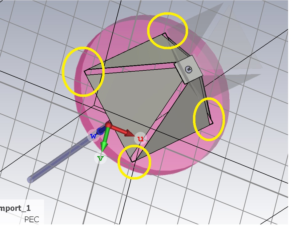
THIS I SEE might be YOUR main problem...(Cut again to eliminate the bridging between CONES , it should be open and the disc is plastic)
-


in Antennas 5GHz band
Posted · Edited by clanon
Me ganaste loco , el mio es de 2020...LMAO!
WHICH ONE you need...? The LPDA you open the 2D DXF (just one) make it double Asign thickness of the material you want (one over the other) and then add a BRIDGE (rectangle sheet at the END , Wide part)
You need an STL from CST and it would open as ALL SOLIDS not materials (dielectric , pec ,etc) designated...and then TWEAK IT...