Register now to gain access to all of our features. Once registered and logged in, you will be able to contribute to this site by submitting your own content or replying to existing content. You'll be able to customize your profile, receive reputation points as a reward for submitting content, while also communicating with other members via your own private inbox, plus much more! This message will be removed once you have signed in.
Dr. Pepper
Members-
Content count
66 -
Joined
-
Last visited
Posts posted by Dr. Pepper
-
-
I crunched the numbers for the all metal antenna (0.5mm thick) and the result is better, but see by yourself (I made the reflector invisible for better view):
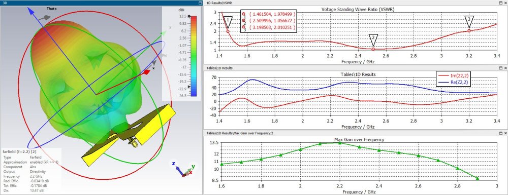
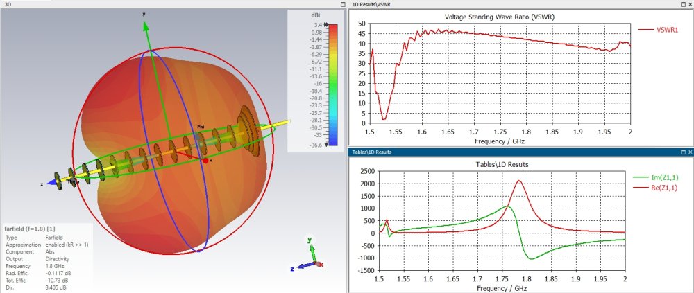
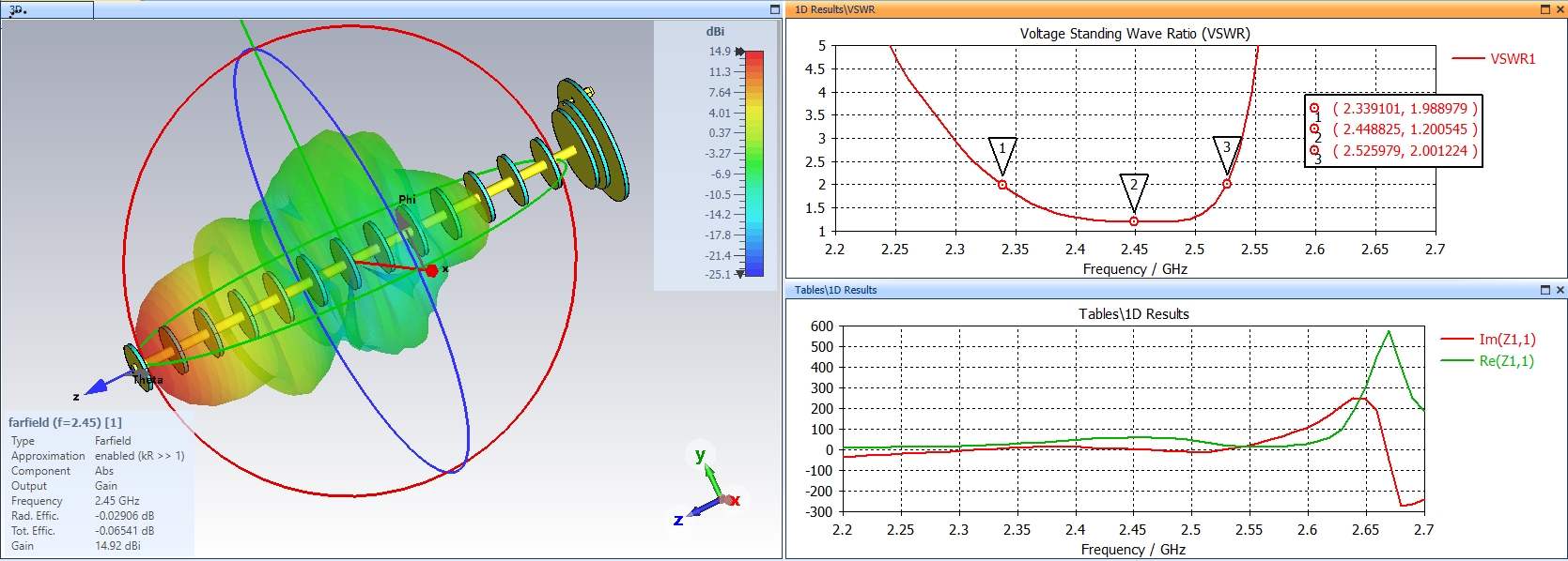
Good gain and a very wide resonance, usable from 1.5 to 3.2 GHz if needed. With this wide band its not avoidable to have this bad swr from 1.6 to 2.3 GHz, I was not able to find a solution where everything is on swr 1.2 or lower. I think for this the antenna has to be recalculated for a more narrower resonance. Its interesting that the peak Gain is still 13.5 dBi, seems to be very stable on this design
1 person likes this -
So here i try to give the dimensions, its not so easy to pick always the right points so dimensions can be off a few µm because of the many layers. I have to add a metal layer of 0.5mm on the sides otherwise the solver produces errors because of the to big mesh size wich results in crashes after a few calculations. So i made the metal layer a little bit bigger. This has later to be considered when printing the inner part (PETG, epsilon 2.6).
Dimensions:
Spoiler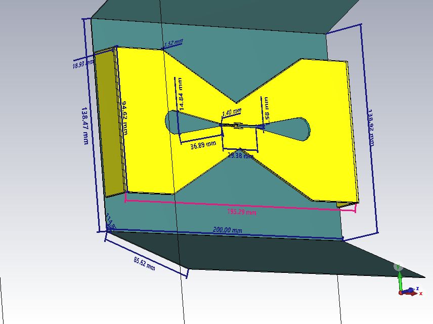
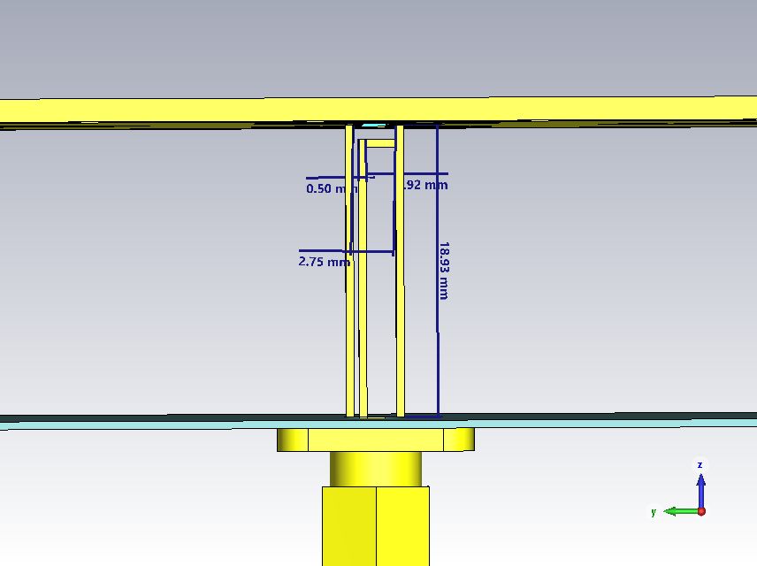
on the second picture the distance is 1.92mm ;-)
I will try what happens when the design is all metal, should be better. The polymer layer is not beneficial
Here also my messy (because of many trial and error) cst file
 3 people like this
 -
I can post the dimensions when im back home or tomorrow, but i will also try a only metal variant. This should even be better
1 person likes this -
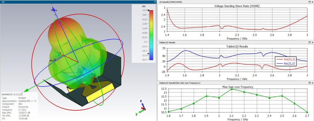
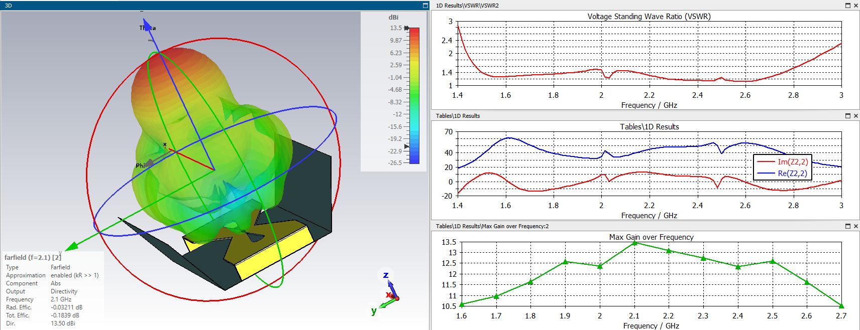
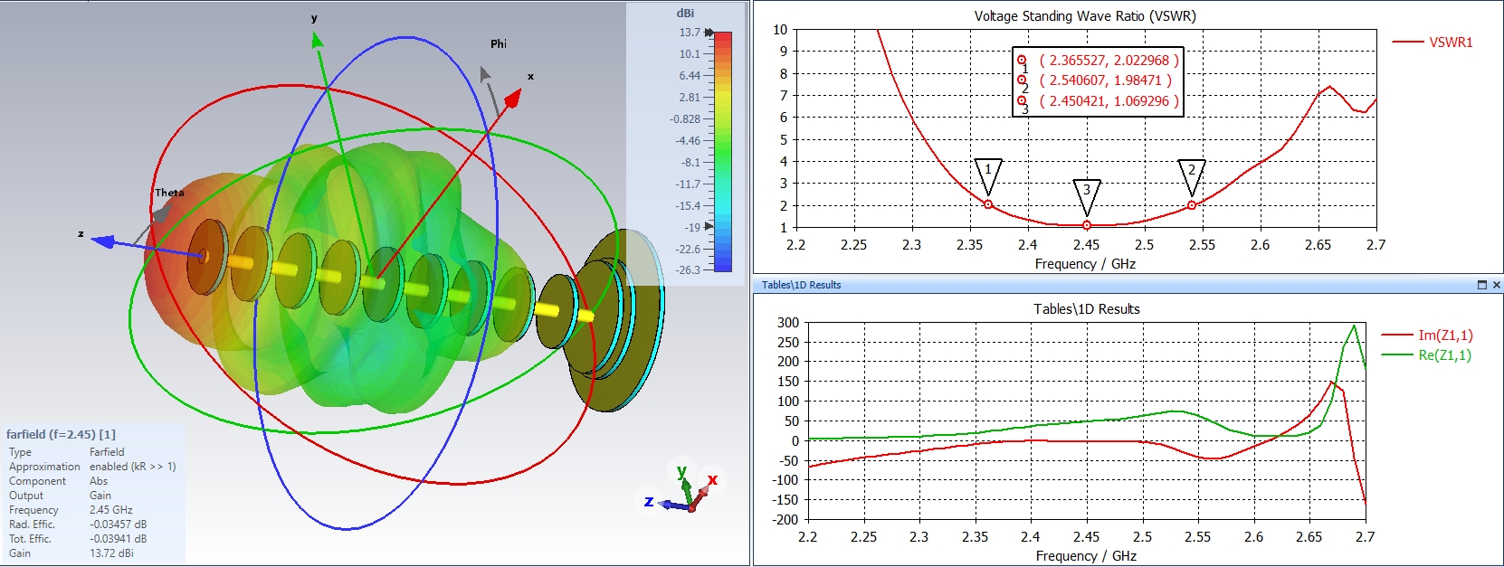
Another variant of this antenna. This time optimized for 3D Printing. The base is calculated as a 1.4mm Sheet PETG covered with copper foil on both sides. This is not as ideal as a full sheet of metal but it can be easy produced even without tools. Its also constructed with a balun which is connected to both sides and sma port. Its quite impressive how broadband such an antenna can be and it gives a max. gain of 13.5 dBi at 2.1 GHz. With the big cut out it goes even more in the direction of a batwing antenna.
 1 person likes this
 -
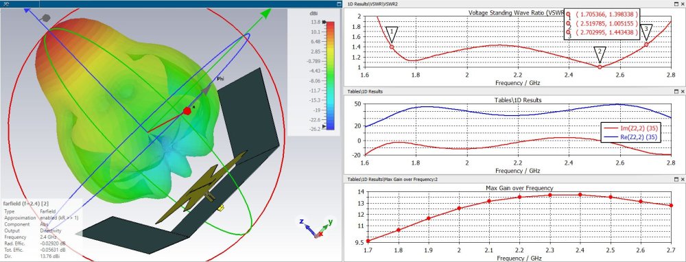
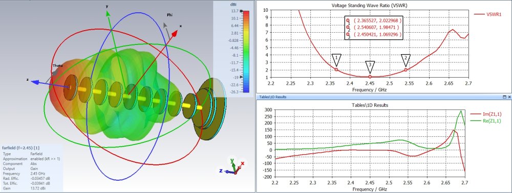
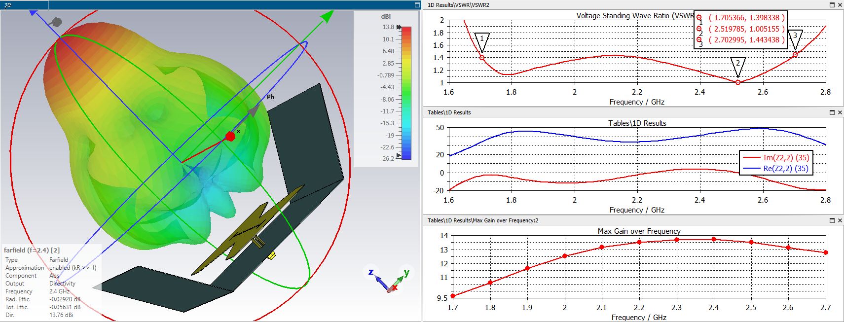
I found a configuration (sides invisible to see the balun) with a wider band but its not much better than the earlier design without the v-cuts on July 2022, good in the old design there is no balun used but I think this should also work with a balun. Only benefit is perhaps the more compact size. But compared to a batwing antenna the gain is slightly better. I think for the cost of a few 0.x dBi the swr could even be lower. When made in 2 pieces it should also be easy to produce this antenna even without expensive tools.
 2 people like this
 -
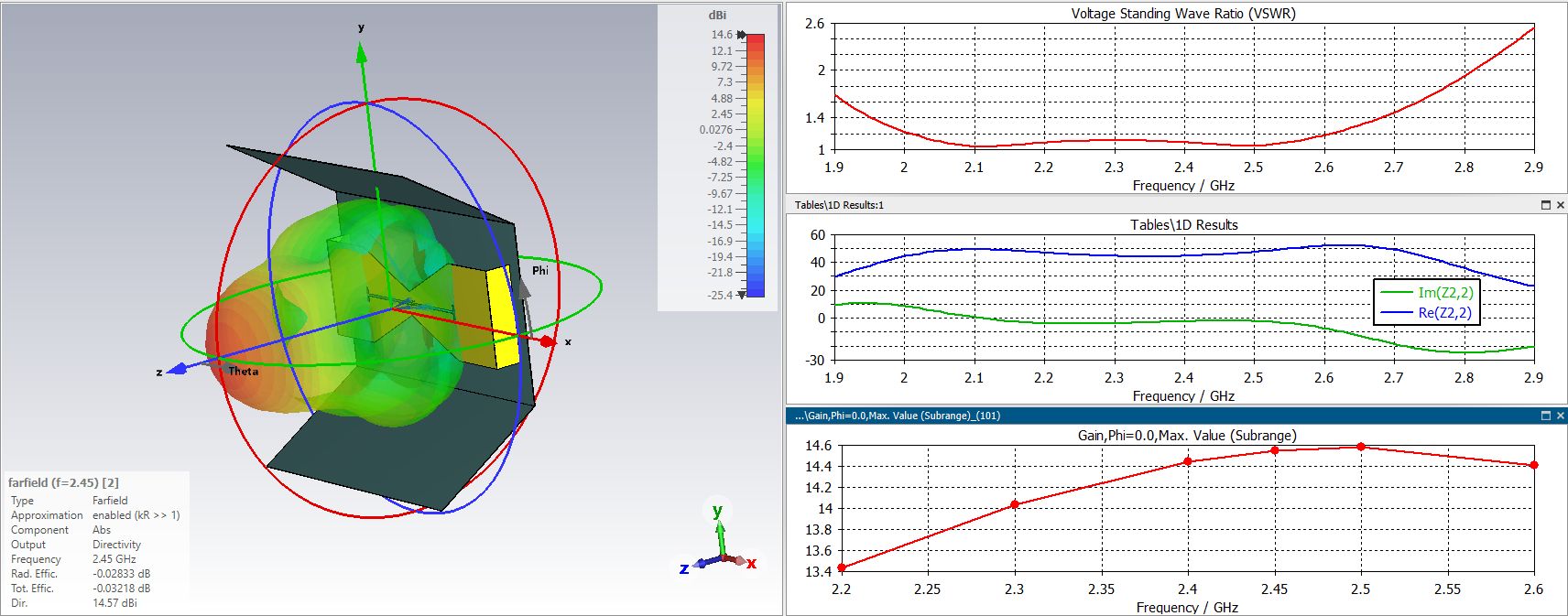
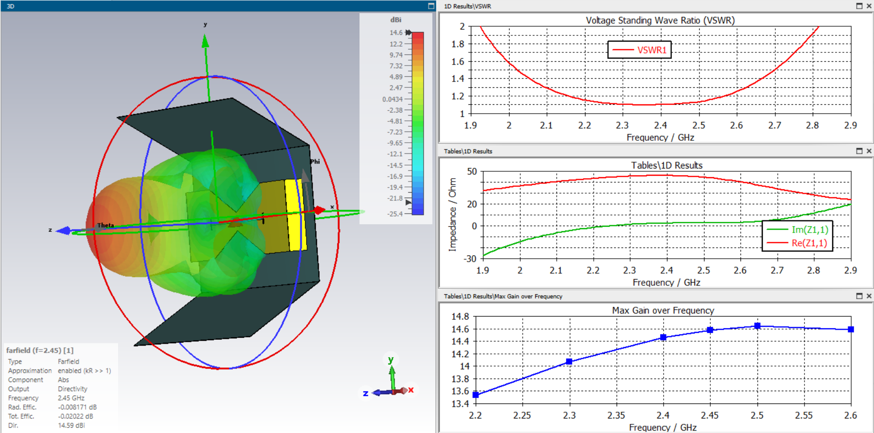
I found some motivation and tried to add a balun to the design to see if this works and with some calculation i found a solution:
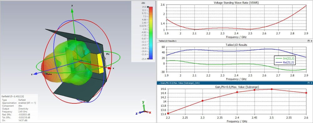
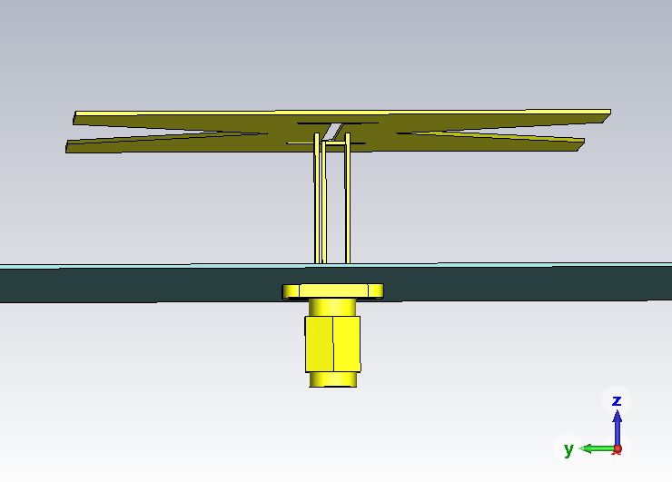
Side view (without legs to get a chance to look inside):
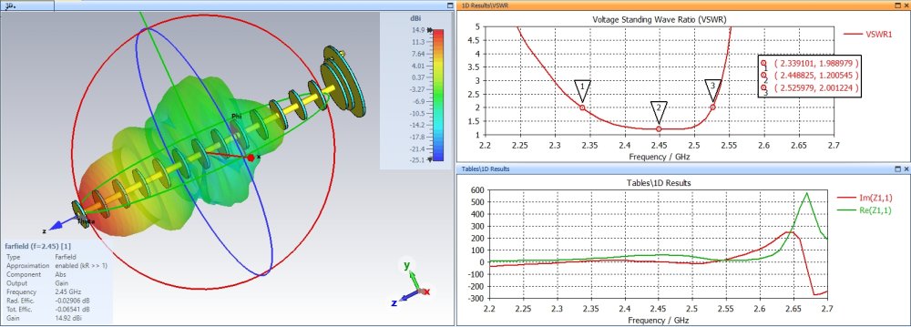
woks quite good, good broadband behavior and a good gain of 14.6 dBi. Its a bit like a batwing antenna
2 people like this -
Could the com666 multiband batwing be an option to cover 800-2700?
-
Here in the forum you can find a lot of information. For example look here:
1 person likes this -
3 hours ago, Admin said: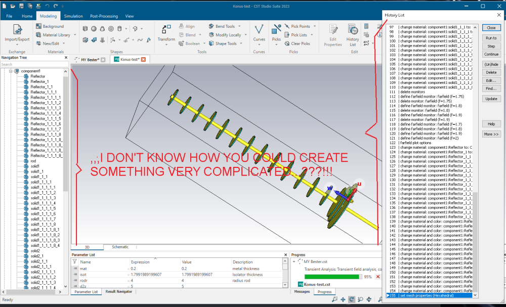
I i didn't see your post, i simply copy translated a director and then scaled it to the right dimension. I messed up the material and color so i changed it afterwards.
I started with the reflector back metal, the insulator and then the second metal and then simply copied it over and over again and resized it
-
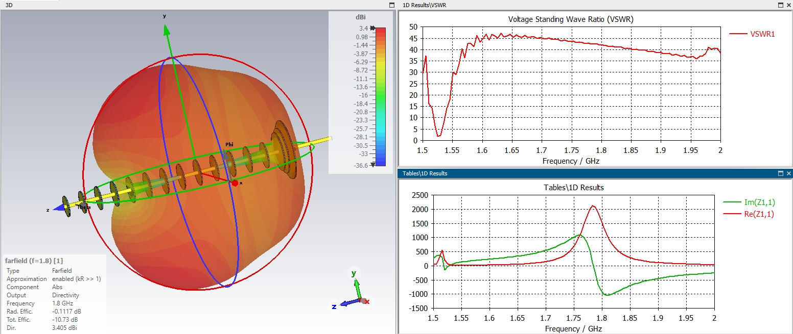
The solution i found with the added konus elements. It works but i couldn't find the claimed 17dbi. At least 15dbi and a good swr of 1.2 is possible.
-
I tried Admins cst file and with this i was able to optimize the structure a little bit. Why my design not works i don't know. I will try to recreate it and find the error. Attached is what i was able to archive with the "konus" antenna, yet the konus is still missing but i will try to add it to raise the gain a little. So it should be possible to make a good antanna even when you only have metal covered plastic disks.
 1 person likes this
 -
I think i have some error with the port, i removed the sma connector and used a discrete port and now the results are much better. I will optimize a litte and look what is possible
1 person likes this -
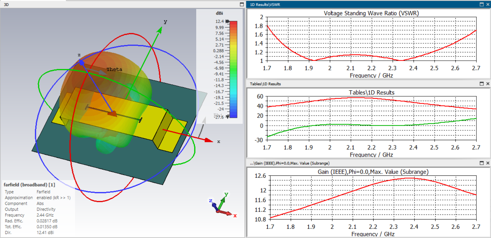
I tried to model the antenna in cst but the design seems not to be right. Can also be that i make a mistake in the design, its a long time since i used the software before. Therefore the parameters are also a bit screwed up. But if you want to look into the design i add the cst file for playing around. When this works it will be very easy to produce such an antenna via 3D printing or with a cheap laser. It is possible to first cut polymer disks and then cover them with conductive tape or simply cut double sided metal covered polymeric material with a cheap laser.
 1 person likes this
 -
Direct visibility is key for range. We tested 15y ago our cantennas in the field and it was no problem to establish a stable connection.
-
Cool idea, this should it make possible to simply 3d print the disks and to cover them with metal tape. When the metal is on both sides then the plastic material it should not produce to many issues because the whole assembly will act like a capacitor with low resistance at 2.4 ghz. But here is even a connection with the center rod so with a new calculation the antenna should perform nearly like a 100% metal one (without looking through the videos to find out if there is a big difference :-).
1 person likes this -
On 7.5.2023 at 1:42 PM, Biruza said:The idea of printing an antenna frame out of plastic can be taken to its logical end. She's very flexible! All antennas are very sensitive to size. It is surprising when the authors give sizes with an accuracy of 0.01. This involves tuning with an SWR meter. In life, it can be done with an accuracy of +/- 0.5 mm.
And if you completely fill the space under the antenna patch with plastic?
The filling can be adjusted, 10-20%, the antenna will be light, but tough. The size will be smaller. The foil is easy to stick on the work surface and cut off the excess. Now the computer is optimizing the batwing from Dr. Pepper.
Directors can be placed upstairsI also try to add more Plastic to the antenna for more stability but the performance was worse. There should be only minimal Material in contact to the antenna. I can only imagine a foam material or something similar, perhaps cutting foam and laminating it with copper tape.
-
On page 12 you will find a calculated batwing for 5ghz, i give there also the dimensions. It also works good at 5.8ghz
2 people like this -
No its not my Database, i only found it and i thought it would be a good idea to make our own.
1 person likes this -
When you are so interested in different designs perhaps its good for you to try cst microwave studio and test your own designs. Not every small change can be tested by our Admin ;-)
-
I think you don't need a mimo configuration. A simple P2P connection is enough to send a few signals to your equipment. When a cantenna is to big, then perhaps a batwing with simple reflector or a slot dipol (Sputnik) should be the way to go. Another possibility would be a simple biquad. All these can be relatively small and fits in a small plastic container. You then only need two network adapters like the alpha card and attach a good antenna on both. One is a hotspot like on your computer one is connected to this from the telescope.
When you can etch pcb's you could also try a pcb biquad. Should be the easiest task to do then. I think 9db gain should be plenty for your application when used on both sides.
 2 people like this
 -
If you only want a connection 600m away on a field you could also simply use 2 Cantennas. I made a fast and stable connection with 2 Cantennas over 7 Km without any problem, but there was nothing in between otherwise such ranges are near to not possible.
1 person likes this -
The angle of the box is very important. It influences not only the gain but also swr, bandwith and so on.
1 person likes this -
The slot dipole with V cut outs like an batwing antenna, not as good for broadband application but a little more compact than the slot dipole and a good gainer. Here an example for a wifi antenna
 2 people like this
 -
Wow that works like charm, thank you.

in Antennas for mobile communications
Posted
I think it can be recalculated for 900MHz. Then also the size will be a little smaller.