Register now to gain access to all of our features. Once registered and logged in, you will be able to contribute to this site by submitting your own content or replying to existing content. You'll be able to customize your profile, receive reputation points as a reward for submitting content, while also communicating with other members via your own private inbox, plus much more! This message will be removed once you have signed in.

eco32
Members-
Content count
78 -
Joined
-
Last visited
Posts posted by eco32
-
-
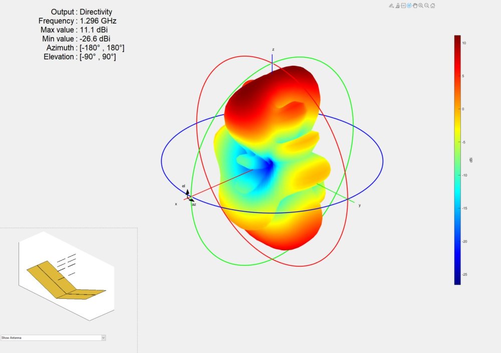
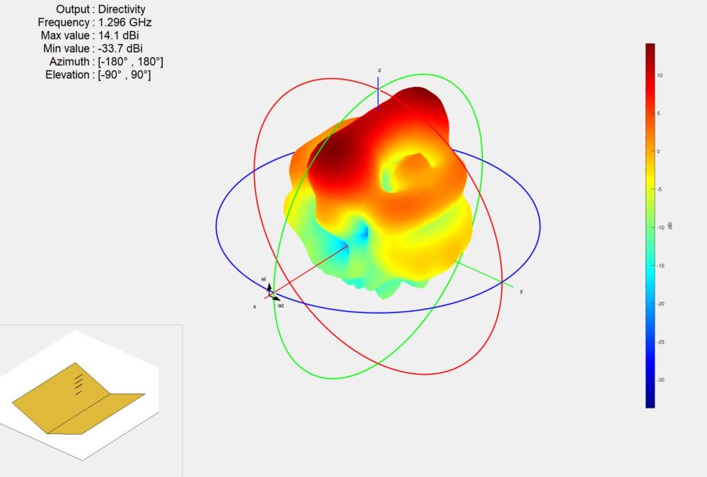
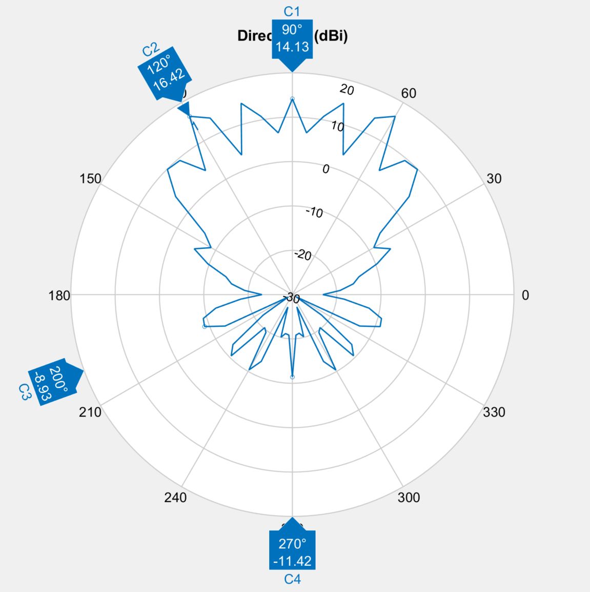
On 15.11.2023 at 4:04 PM, Admin said:,,,executes a single reflector with two antennas spaced at a distance greater than 143 mm between them...!!!
10dBi in main direction, same a single dipole with corner reflector
-
two dilpes with corner reflector: Gain increases, but at the expense of side lobes, in some applications this is unacceptable
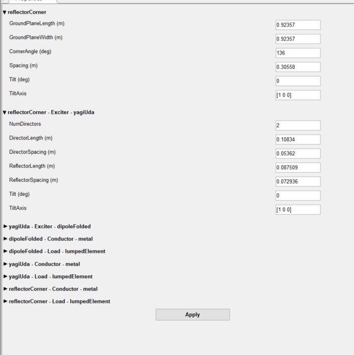
details: Yagi feed is reversed and it has two reflectors
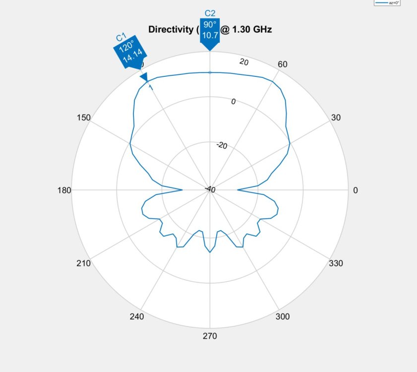
side lobes:

how it looks in "normal mode:, feed litle yagi was not reversed:design:
patern

-
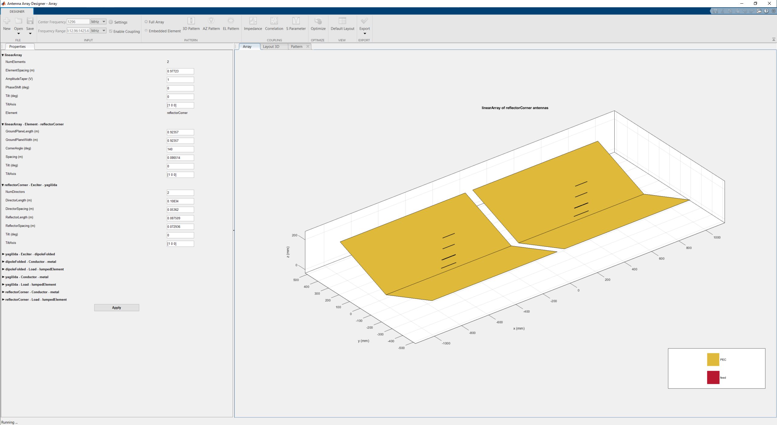
19 minutes ago, Admin said:,,,eco32, what program do you use for simulation...!!!
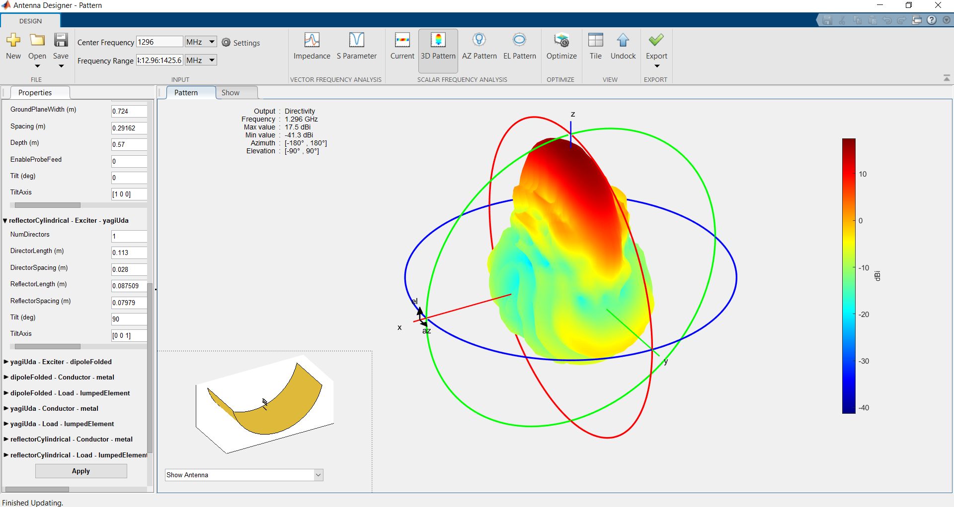
Matlab (not yet able to use CST)
-
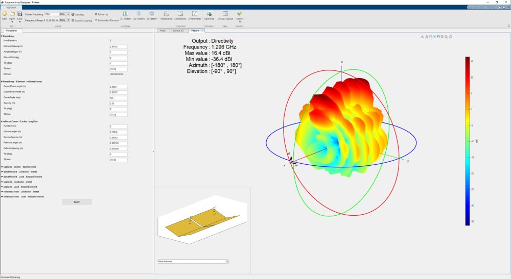
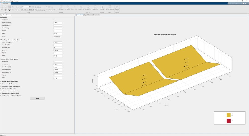
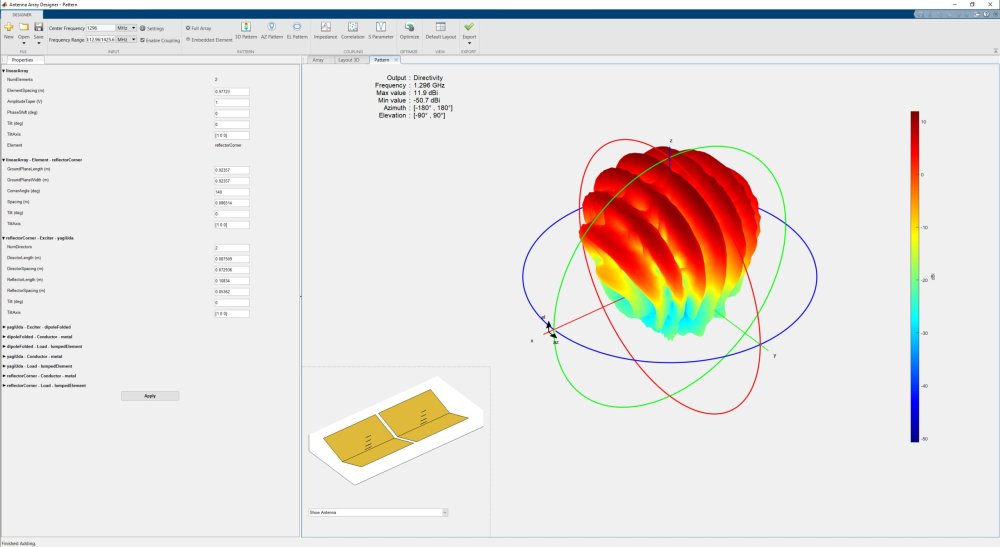
Simple design with a corner reflector. 14dB, 10dB in the main direction, with additional work with the elements, you can probably improve the main beam. The structure is similar to my latest grid (17dBi), but simpler. Important detail : standard model feed was changed to revers direction of radiation - director is Reflectors and reflector is director. Useful when you don't want to build a parabola

-
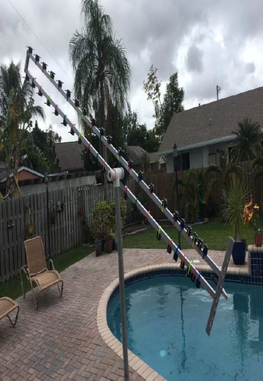
Lets continnue long hi gain Yagi for a 1296MHZ (it may by scaled for LTE or WIFI), these publications look better than those I pasted earlier [1-5]
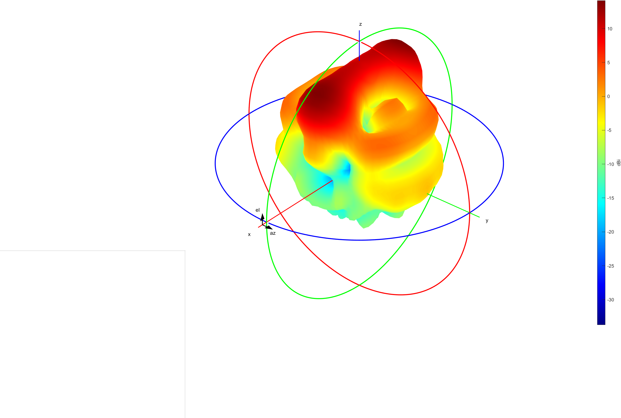
[6] Randy, K9BCT he build Hybrid Biquod for EME, 2x200cm boom and 19dBi (extended version of biqoud hybrid Yagi DL7KM)
"47 element version (44 directors, 2 loop DE and reflector) has a version (44 directors, 2 loop DE and reflector) has a relatively impressive frontal pattern with over 19dbi relatively impressive frontal pattern with over 19dbi"
other parameters:
F/B, almost 34db.
G=19.17 dBi
TA=31.5 K
Tloss=3.0
K=3.0 K
G/T=+4.20 dB..
Impedance is 49.--0.162j ohms
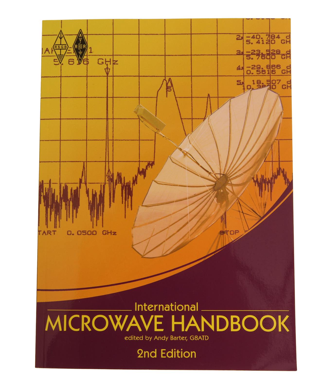
[7] - International Microwave Handbook - (I have only few pages, if someone has full book, please share before i will buy
") )
)

it looks like You can not achive more dBi than on this chart will let You. (BTW Antenna from [7] biqod hybrod Yagi 2x200cm boom 19dBi looks good
-
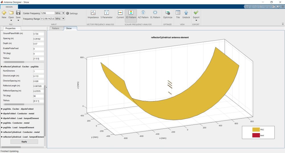
5 hours ago, Admin said:,,,2 coupled grid parabolic antenna (600x800mm)...!!!
No, We all know it was stupid idea. (Bad shape)
6 hours ago, clanon said:REFLECTOR SIZE ! (and SHAPE) that's where the 17 dbi come from...
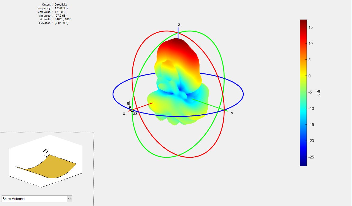
It is based on Pacyfic Grid 917x720 and 15cm deep 5.6GHz grid antenna symulation + Yagi Uda in revers - directors works likea rediators (This is not a good representation, Matlab has big limitations)
1296MHZ => 17.3dBi
oryginal grid antenna https://www.cyberbajt.pl/produkt/350/pacific-grid-56-ghz28-dbi.html
2 people like this -
41 minutes ago, Admin said:Thank You!
This will help me a lot
-
1 hour ago, Admin said:,,,yes, but it seems to me that the gain is too small for an antenna with so many elements...!!!
It looks like my 90cm quassi dish (grid from 5GHz grid antenna) with dipole feed with coaxial splited balun has biger gain ans smaller dimeters
Looks like 17dBi gain in loop is a naive wish of the author. Let me try.
I have CST studio for a short time, I don't know how to use yet. Please be kind and share this model, I will try to change the diameters of the elements and distances one by one
 1 person likes this
 -
additional materials
[4] A Parasitic End-Fire Array of Circular Loop Elements
[5] Optimum Design of Yagi Array of Loop
-
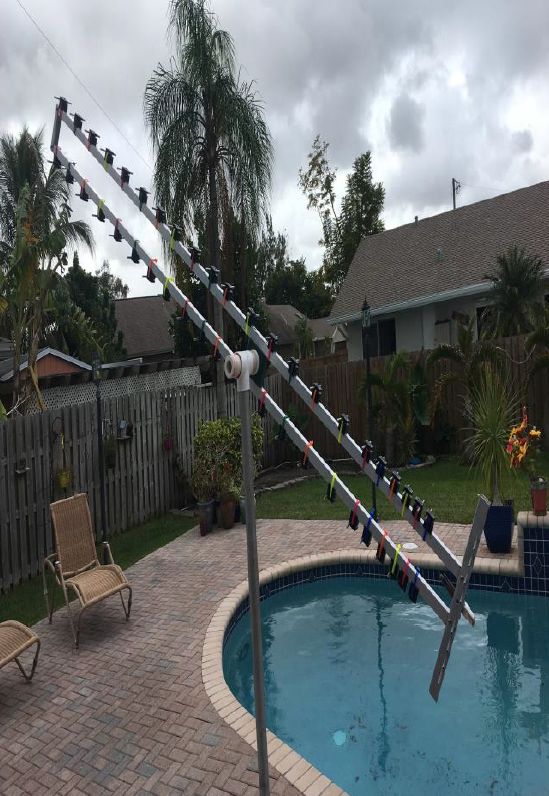
Before simulating and building the antenna, I wont to learn something about the principles of selecting elements.
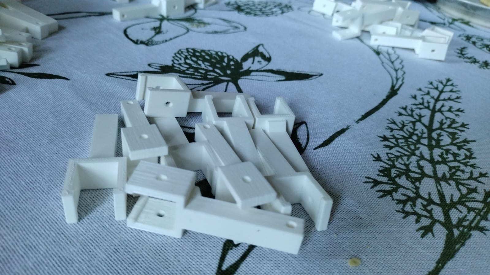
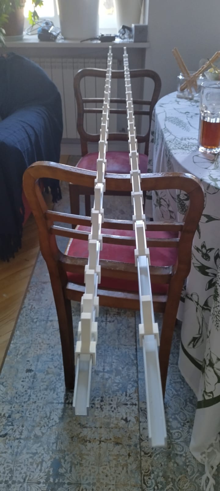
I have two booms of 2m each and 40 printed insulated supports for antenna.
I assume that it will be possible to achieve more gain from loop antennas than from traditional Yagi Uda.
sources:
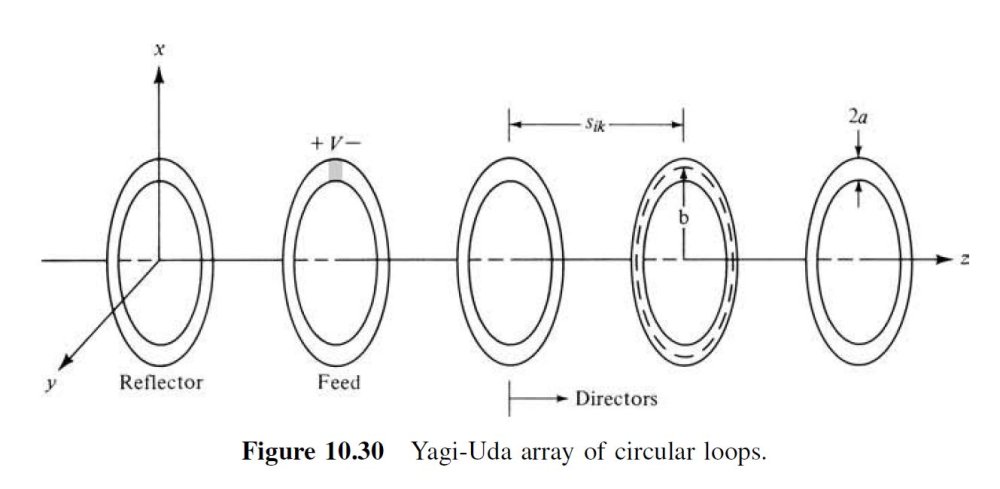
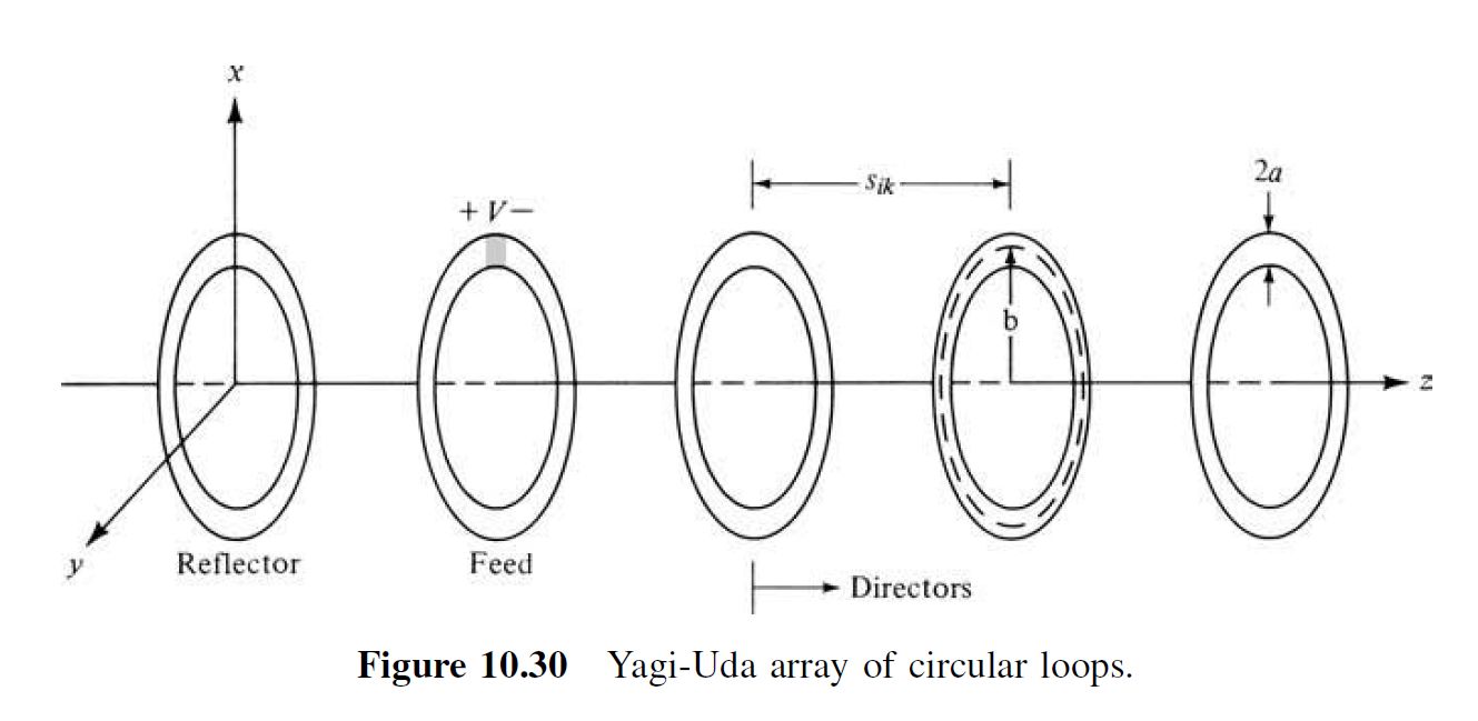
[1] Balanik Antenna Theory (2th)- 10.3.4 Yagi-Uda Array of Loops - page 597
Ina numerical parametric study of coaxial Yagi-Uda arrays of circular loops [37] of
2 to 10 directors, it has beenfoun d that the optimum parameters for maximum forward
gain were1. circumference of feeder 2πb2 1.1λ, where b2 is its radius. This radius was
chosen so that the input impedance for an isolated element is purely resistive.
2. circumference of the reflector 2πb1 1.05λ, where b1 is its radius. The size of
the reflector does not strongly influence the forward gain but has a major effect
on the backward gain and input impedance.
3. feeder–reflector spacing of about 0.1λ. Because it has negligible effect on the forward
gain, it can be used to control the backward gain and/or the input impedance.
4. circumference of directors 2πb 0.7λ, where b is the radius of any director and
it was chosento be the same for all. Whenthe circumference approached a value
of one wavelength, the array exhibited its cutoff properties.
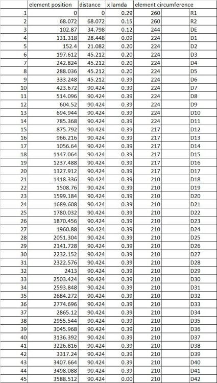
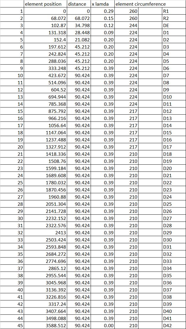
5. spacing of directors of about 0.25λ, and it was uniform for all.[2] NTMS 12' (45 Element) And 6' (25 Element) 1296 MHz Loop Yagi Club Project 1979 (I haven't found anything newer)
https://pdf4pro.com/view/1296-loop-yagi-dimensions-ntms-1a4d92.html
Elements Length
R1-R2 10.23”
DE (brass) 9.59”
D1-D11 8.81”
D12-D17 8.55”
D18-D25 8.25”
D26-D42 8.25”[3] Efficient Modeling of Radiation and Scattering for a Large Array of Loops

.thumb.jpeg.d0f7f8841f7c6b84839e770c9f04f767.jpeg)
 1 person likes this
 -
Vivaldi in progres, Im waiting for bigger drill
I do not know completely what the result will be, I make from garbage.
-
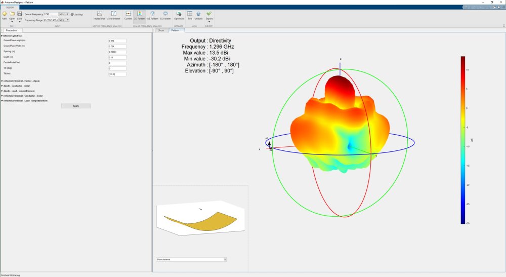
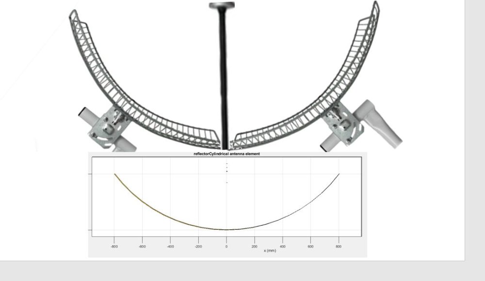
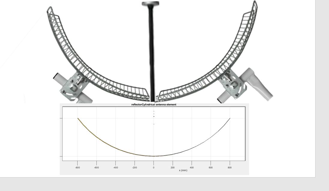
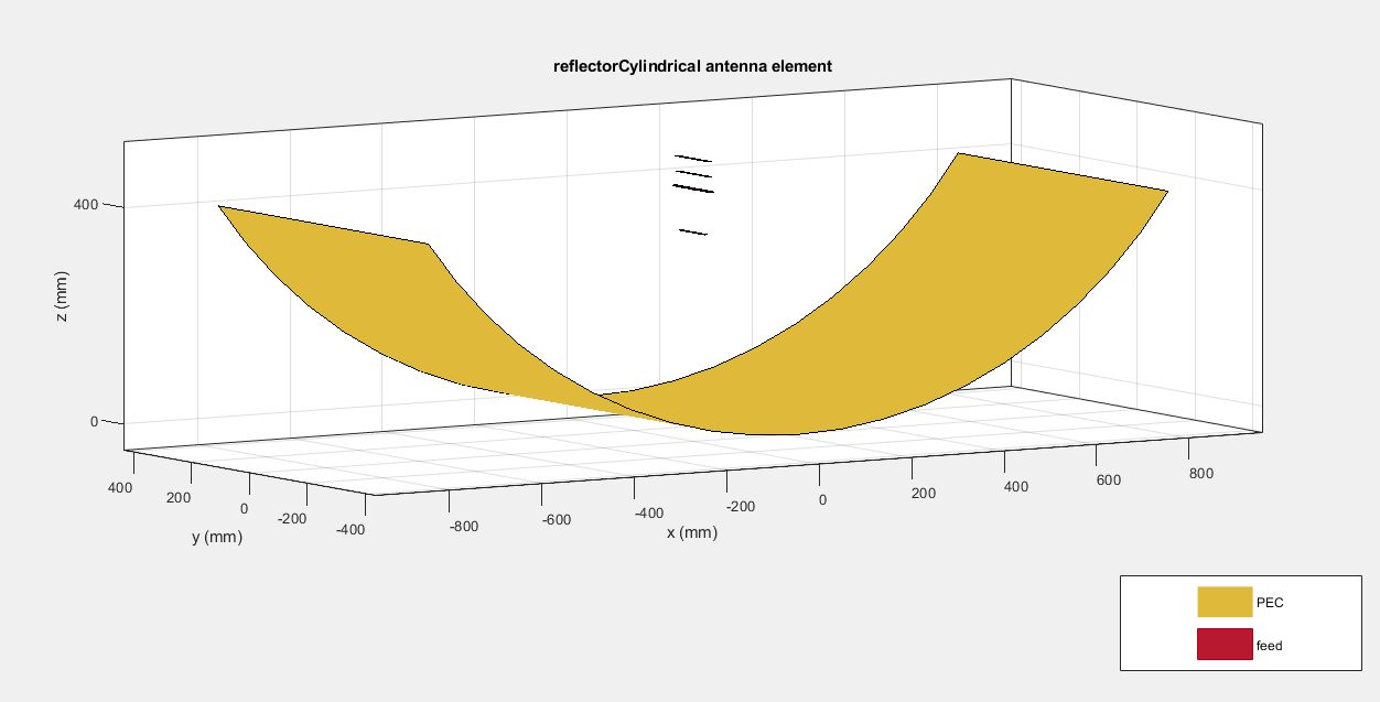
conclusion from simulations and from experiment:
shape is ok, gemetry is wrong!

Why?
The ratio of focal length to aperture size (ie., f/D) known as “f over D ratio” is an important parameter of parabolic reflector. Its value varies from 0.25 to 0.50. calculator: https://satlex.de/en/fdratio-params.html?diam=90&depth=15
in my case is f/D = 0.16 => Geometry is wrong - may it be that with other type of feed will be more profitable. Any parabolic antenna larger than 120cm is horrendously expensive, building big grid antennas is reasonable.
Example from Czech Republic: https://www.ok2kkw.com/wsjt2006/23cm2008.htm also for Earth–Moon–Earth communication (EME).
Grid vs double grid with siple dipole fed without small reflector as case above 13.5dBi VS 17dBi

I DID IT, AND YOU DONT HAVE TO!
1 person likes this -
23 hours ago, anoduck said:@eco32 Just restating to make sure I understand this correctly. If I hold a lazer where the bester is, the lazer should hit the dish, and reflect off the dish. Then a piece of paper can be used to show where the beam of the lazer is reflected to?
how to finf focal point:
you point the antenna towards the sun, and sliding cheet of paper (I couldn't find a better source to ilustrate)
LASER use:
-
It was concept picture, it has one focal point
-
9 minutes ago, Admin said:,,,this is a bit stupid..!!
This requires an explanation as to why you think it is stupid.
11 minutes ago, Admin said:,,,you'd better use a parabolic offset...!!!
Of course not, such a grid reflector is best for dipole feed that have parabolas smaller than 10xlambda
BTW, it is prototypingc, parabolic offset will be consider in other project. Here we consider the "siple dipole" feed and exploration, what we can do. @Admin do you agree with me?
-
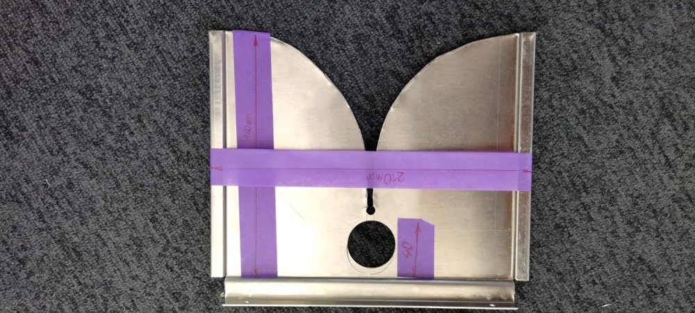
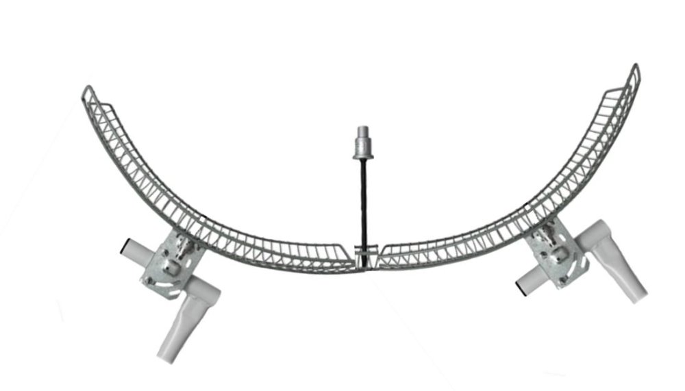
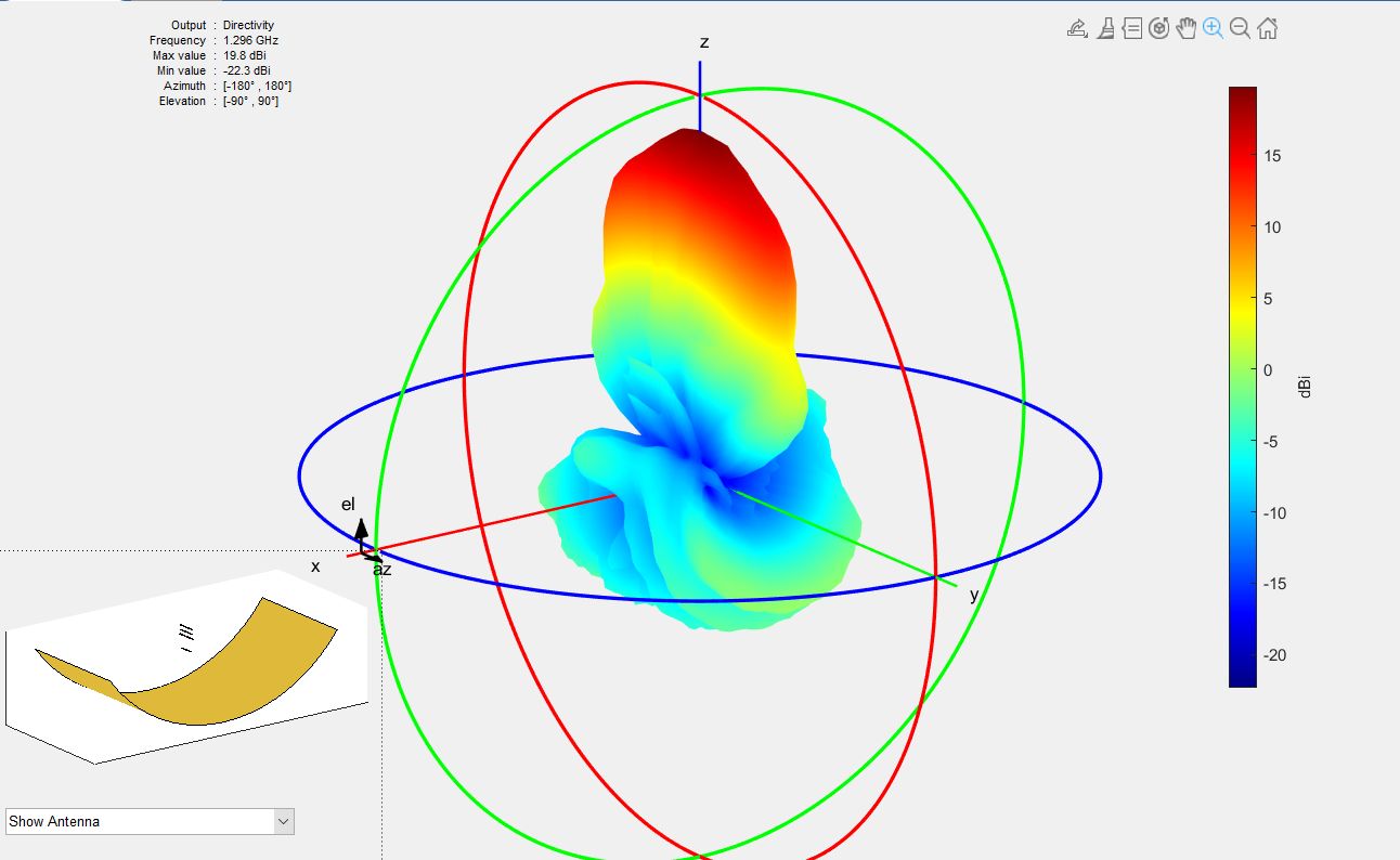
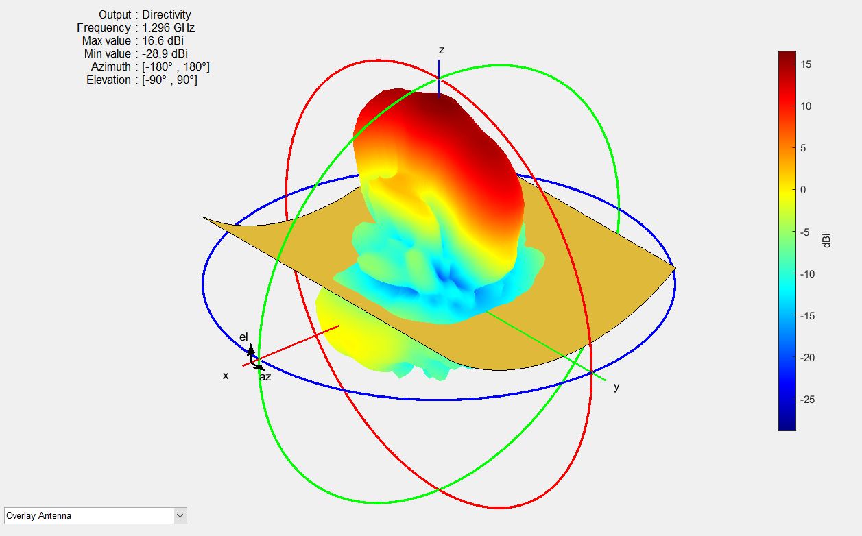
Measured very roughly, when the dimensions of the system are accurately measured the results will be different
Thats the basic grid - 17.3 dBi
That's double grid: 19.8dBi


option B - it does not work: 16.9dBi

conclusion: doubling the reflector area gives ~~~~ 2.5dBi or more of the gain.
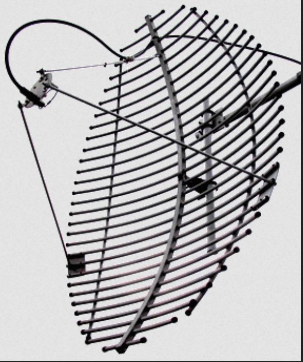
I will show real pictures later, will be mechanically difficult.
I think I can get a few dB more by improving the feed.
-
1 hour ago, Admin said:such a thing is not possible...???!!!
That's what my fellow senior radio amateurs tell to me
1 person likes this -
I have two same grids, lets fin out how it will be in thi combination (simple ilustration):
(simulation without optymalization shows inceasing gain from 17.2dBi to 19.6dBi)
 1 person likes this
 -
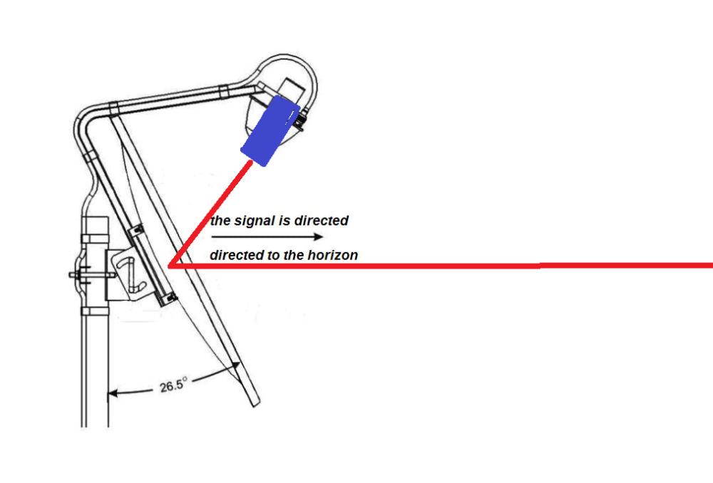
17 hours ago, Admin said:,,,your offset antenna is not well positioned for terrestrial reception...!!!!
@Admin has right
@anoduck: You can use siple laser pointer to findout where your beam is radiating. focus point can be checked by peaper sheet and sun
focus point can be checked by peaper sheet and sun.
BTW: The sun generates a lot of noise and pointing the anena at the sun You can also adjust the focal point.
1 person likes this -
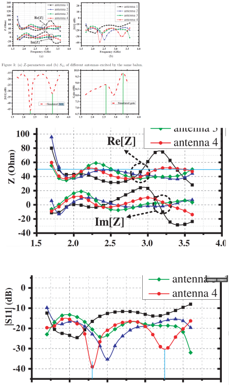
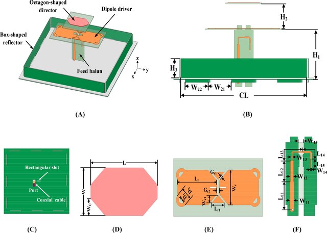
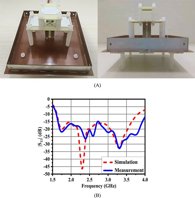
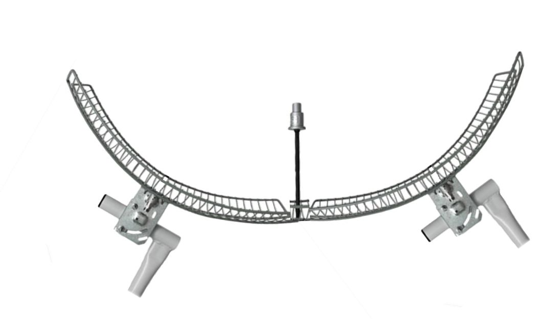
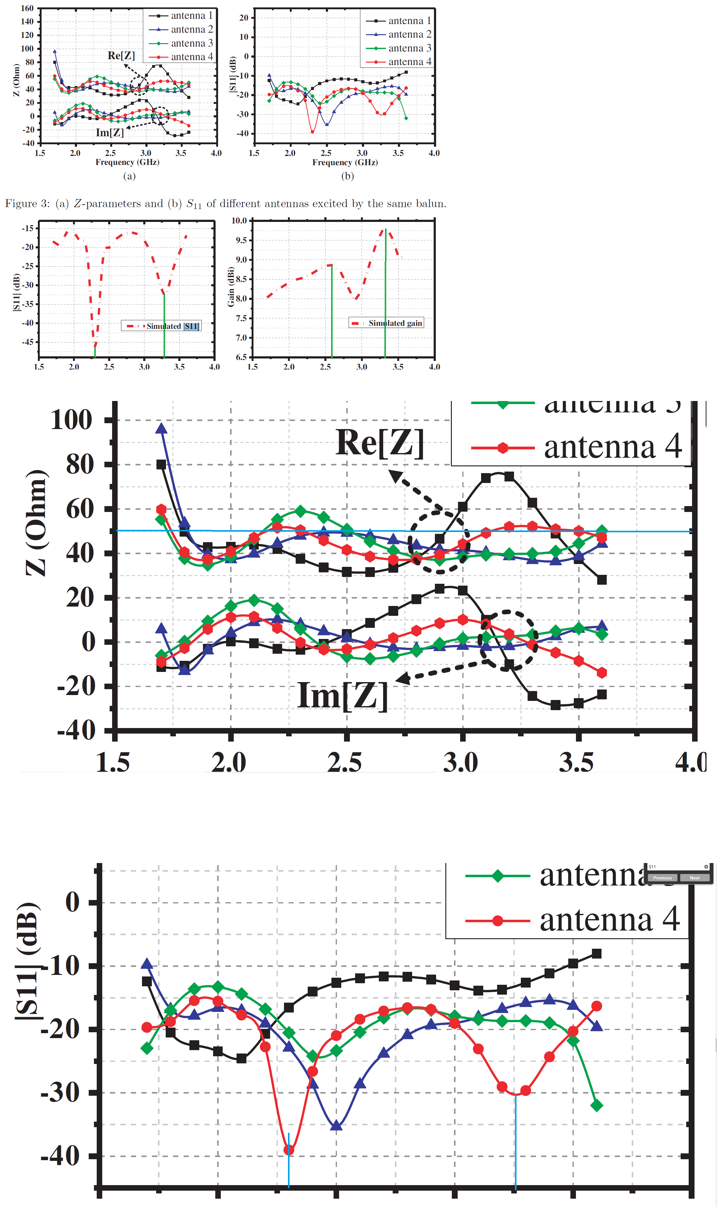
I have acces only to "A Novel Wideband Quasi-Yagi Antenna for Base-station Applications", the is no dimensions.
From charts it looks like this is antenna for a ~2.3GHz and ~3.3GHz
-
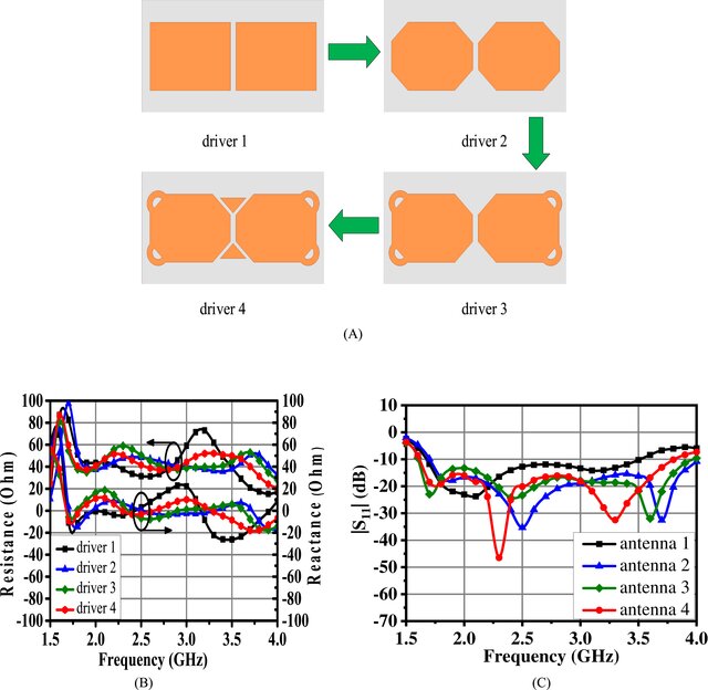
from documents:"Wideband quasi‐Yagi antenna with stable radiation patterns for base‐station applications" and "A Novel Wideband Quasi-Yagi Antenna for Base-station Applications"
> simulated gain ranges from 8.0 dBi to 9.8 dBi in the operating band.
that is same gain as in simple biquad but a simpler design.
-
On 4.06.2023 at 6:03 PM, Admin said:,,,nothing happens...!!!
Is there a director shape that works best, a square, a loop, a simple rectangle , (...)?
-
In my understanding of MIMO, these antennas transmit separate signals, +45 and -45degr, in the simulation should be considered separately and not together. Gain will be 6dBi, not 9dBi.
-
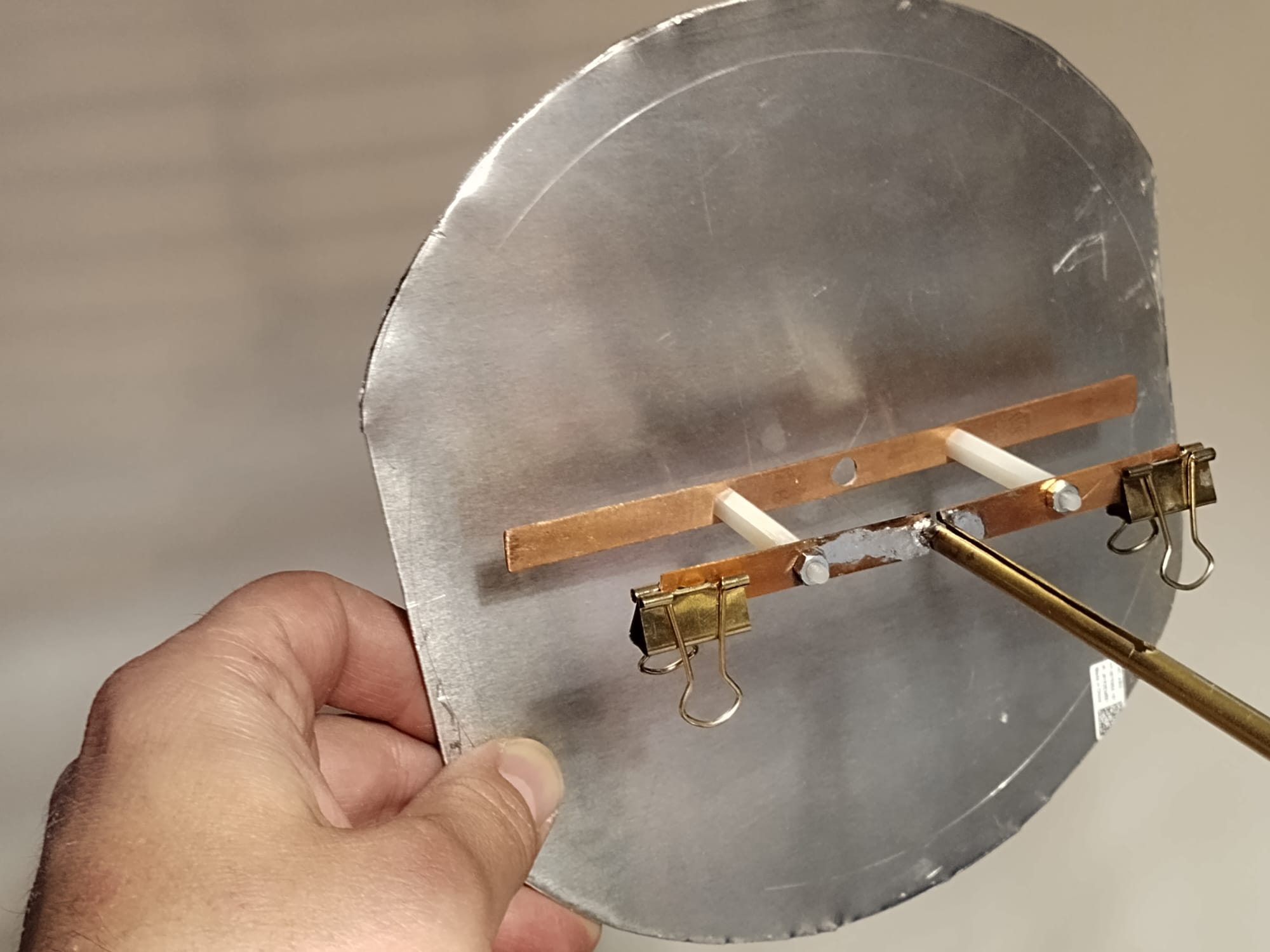
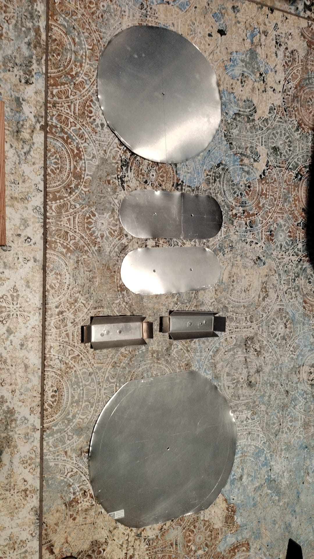
Prototyping ongoing
.thumb.jpeg.f8d59176993be4c96bbf48e1dcc98eda.jpeg)

 1 person likes this


.jpeg.be051d0330c6db2171fbf3c95b2796f2.jpeg)


.jpeg.296a81980317f389edab3068f8e9b314.jpeg)
in Antennas for 2.4 GHz band
Posted
Thats the biqaod, is there an chance to achive circular polarisation with two biqoad or biloop antenas using only phase shifter?
(two biquads oriented at 90 degrees to each other)