Register now to gain access to all of our features. Once registered and logged in, you will be able to contribute to this site by submitting your own content or replying to existing content. You'll be able to customize your profile, receive reputation points as a reward for submitting content, while also communicating with other members via your own private inbox, plus much more! This message will be removed once you have signed in.

Harry36
Members-
Content count
179 -
Joined
-
Last visited
Posts posted by Harry36
-
-
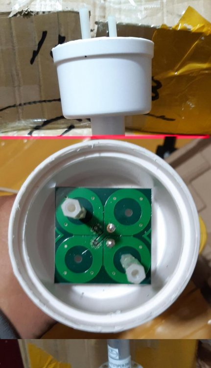
It's MIMO 4*4
")
-
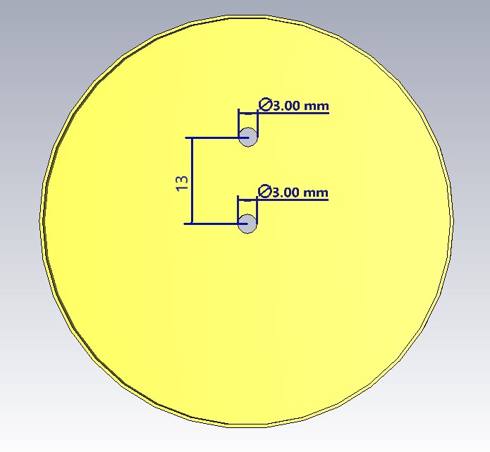
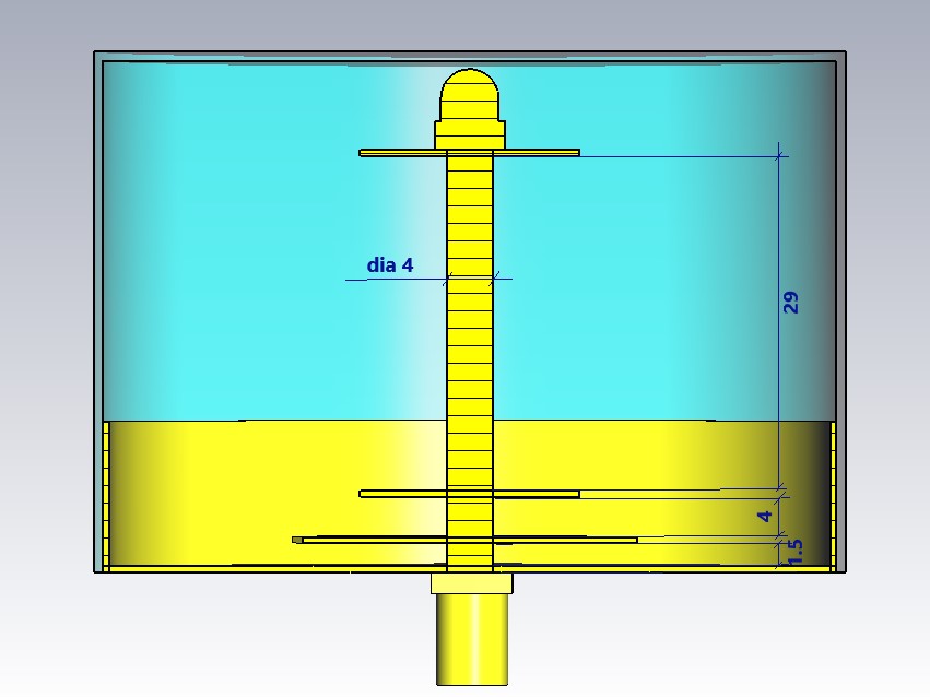
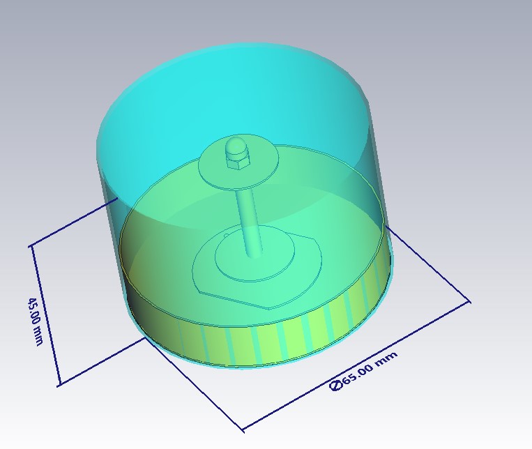
The antenna has an impedance of 75 ohms, in the model the port is -50 ohms. Is the design not original? In the original, the antenna is offset from the center of the reflector. The radiation pattern deviates from the normal ~ 5 degrees.
-
40 minutes ago, clanon said:.thumb.jpg.5fa2d59b61862ca3381b3841a48a5b73.jpg)
different feeding. in the first variant - direct feed (you need a balun), in the second case - Y probe. the second option is the overlap in terms of 1700-2900. but the dimensions must be multiplied by 2+
 1 person likes this
 -
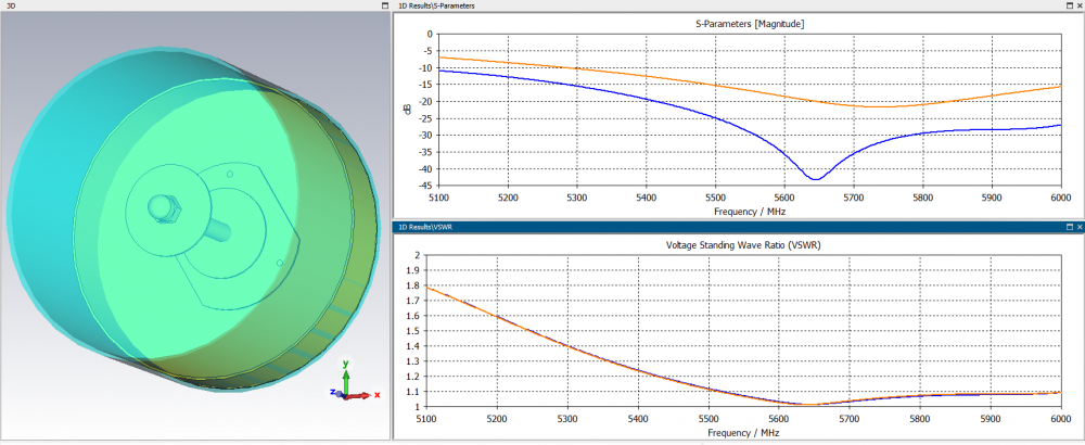
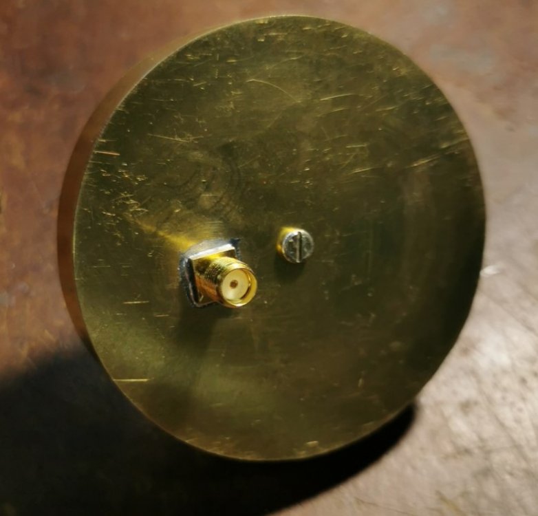
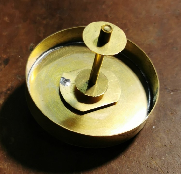
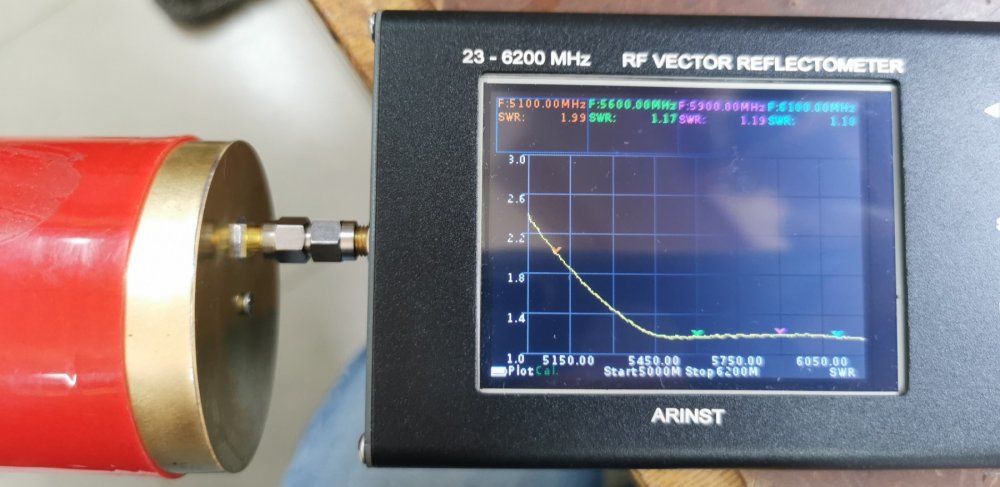
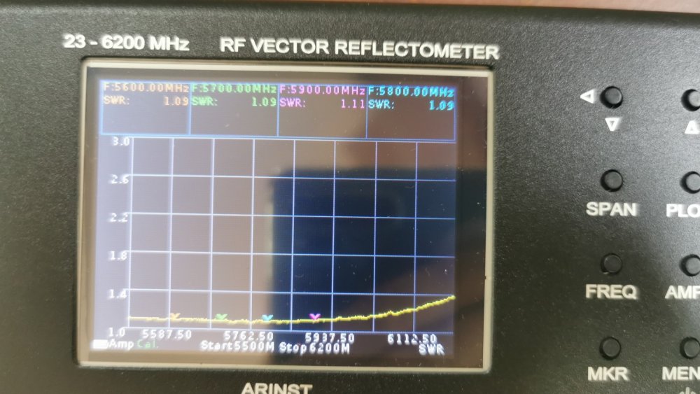
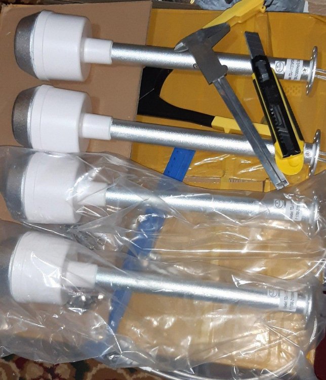
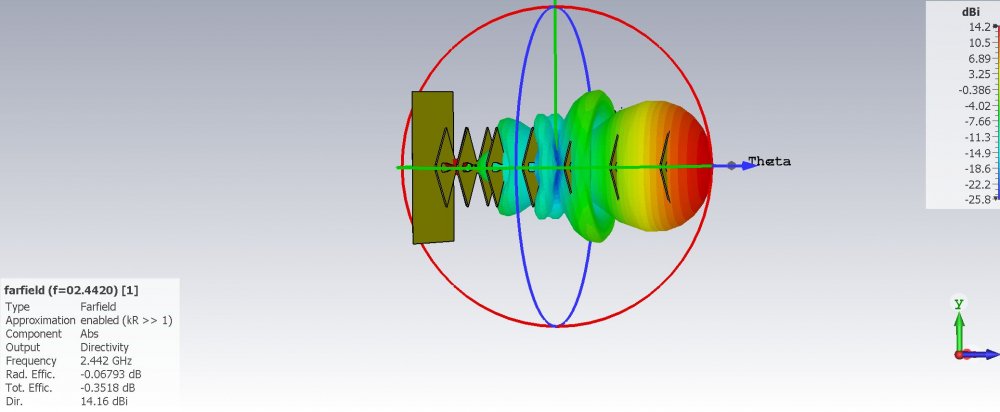
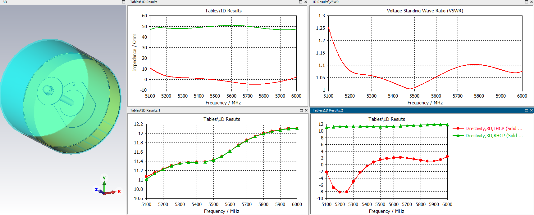
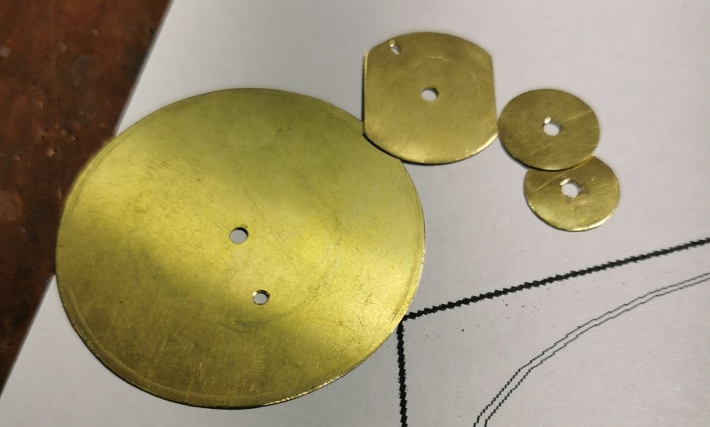
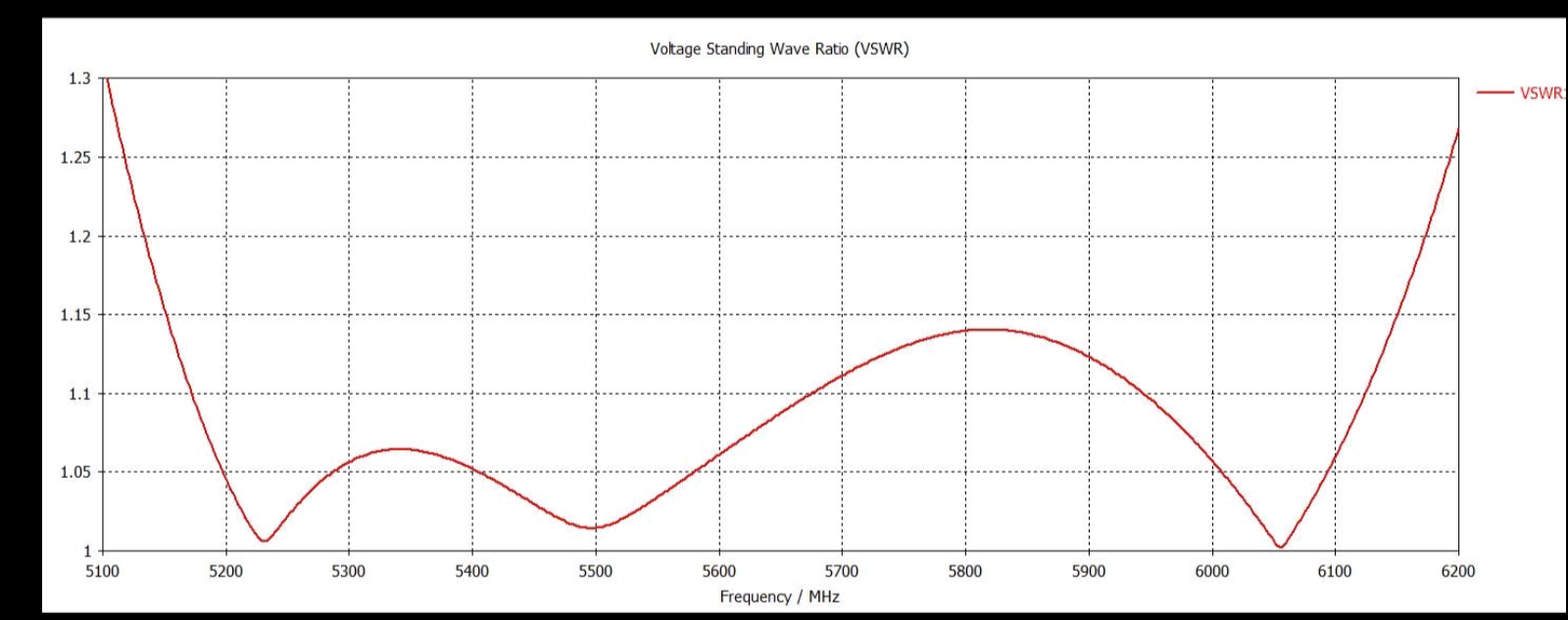
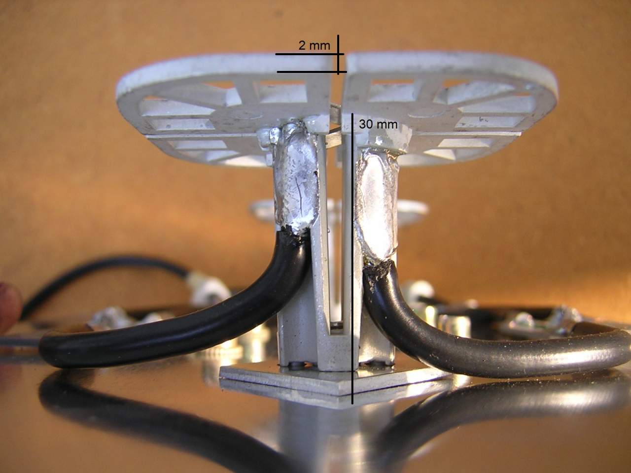
Simple antenna with small dimensions and 12dBi gain for FPV (5600-6000 MHz). Circular Wave Polarization Antenna (RHCP).
bonus: wi-fi 5150 - 5825.
siso:

and mimo:
sizes:
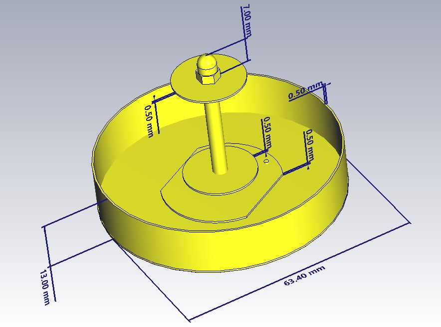
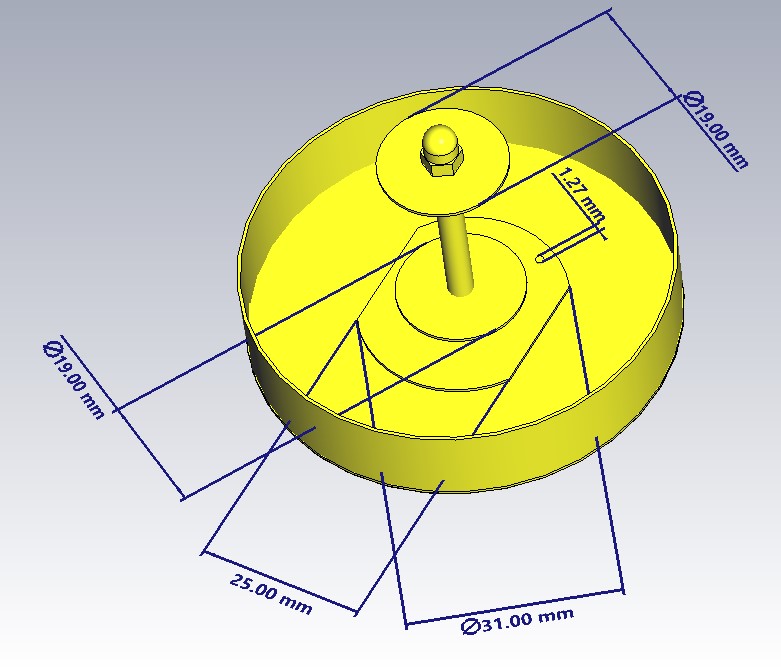
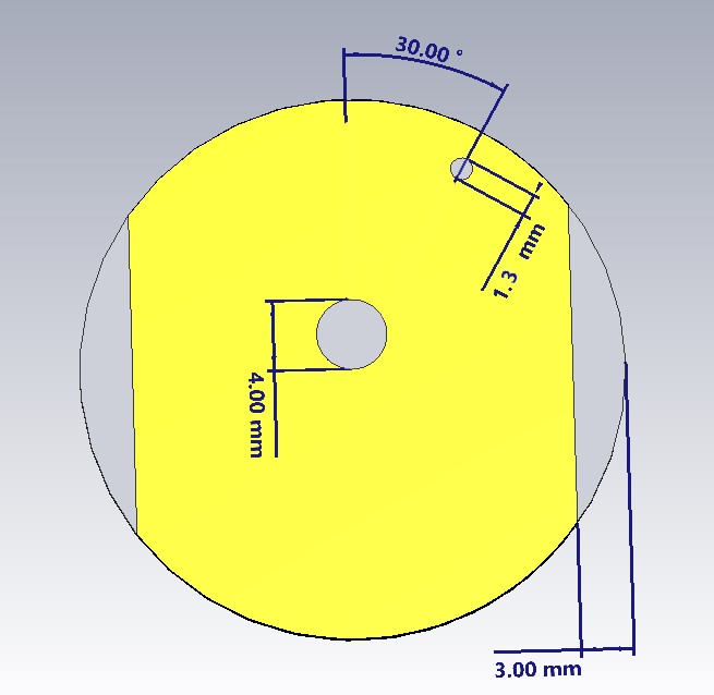
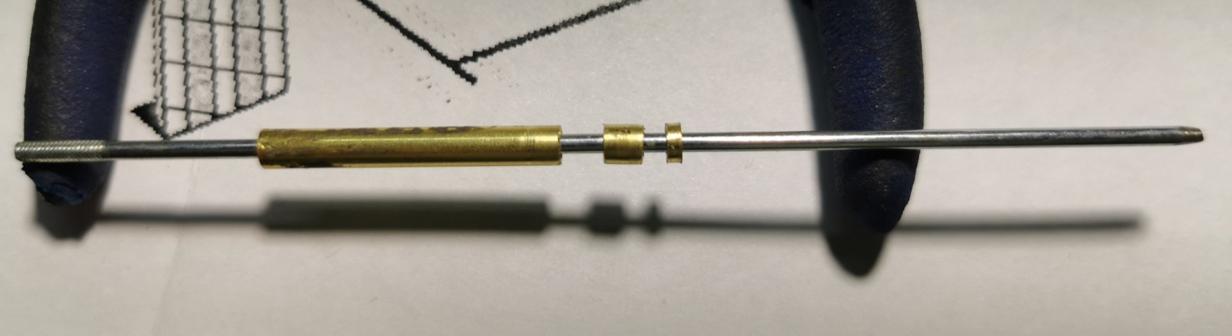
DIY
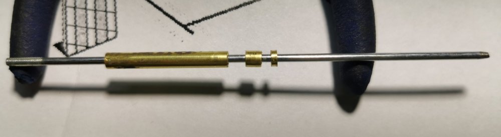

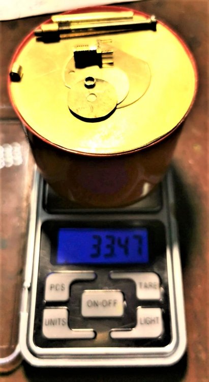
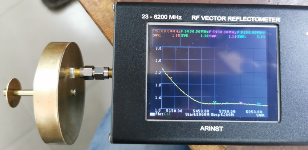
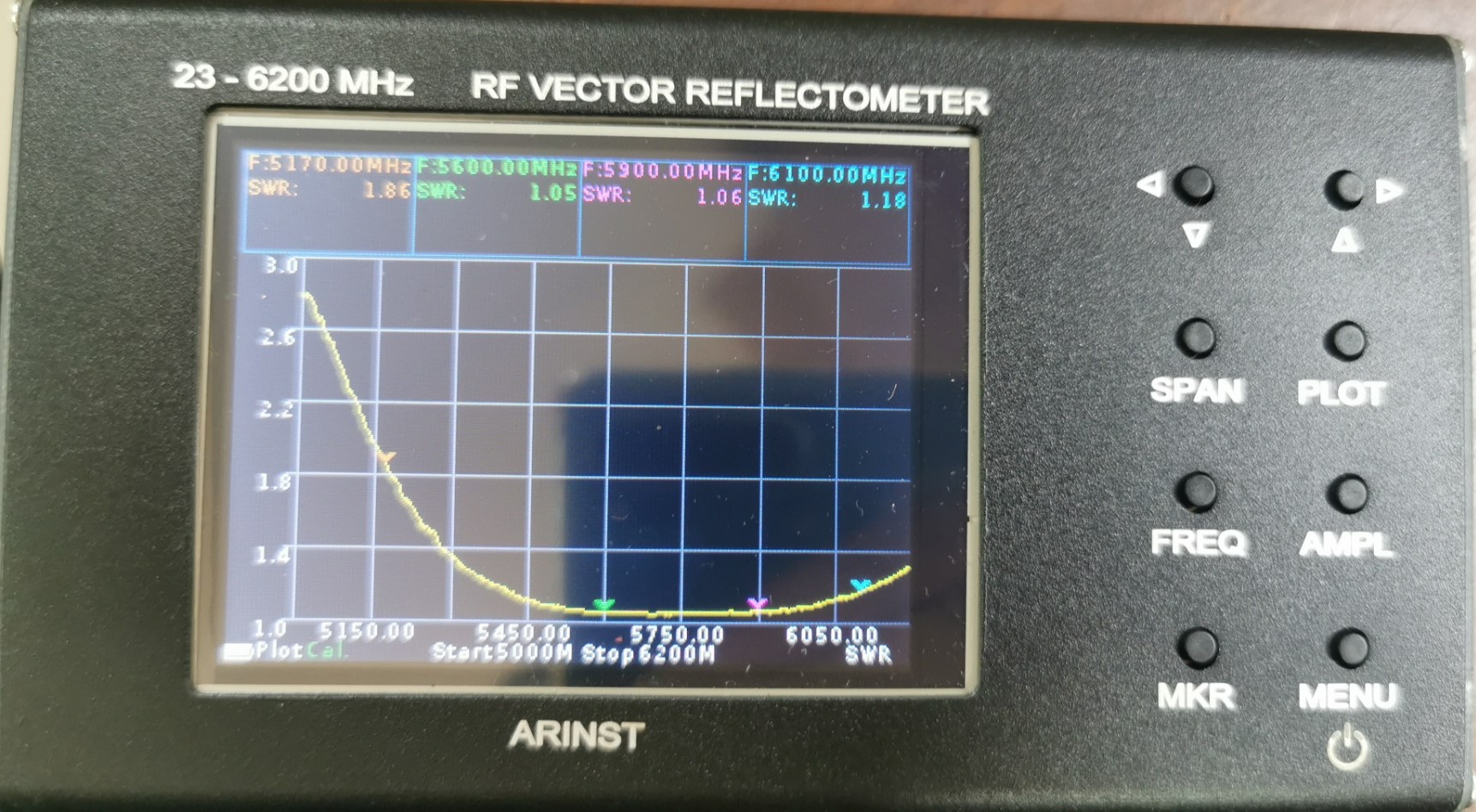
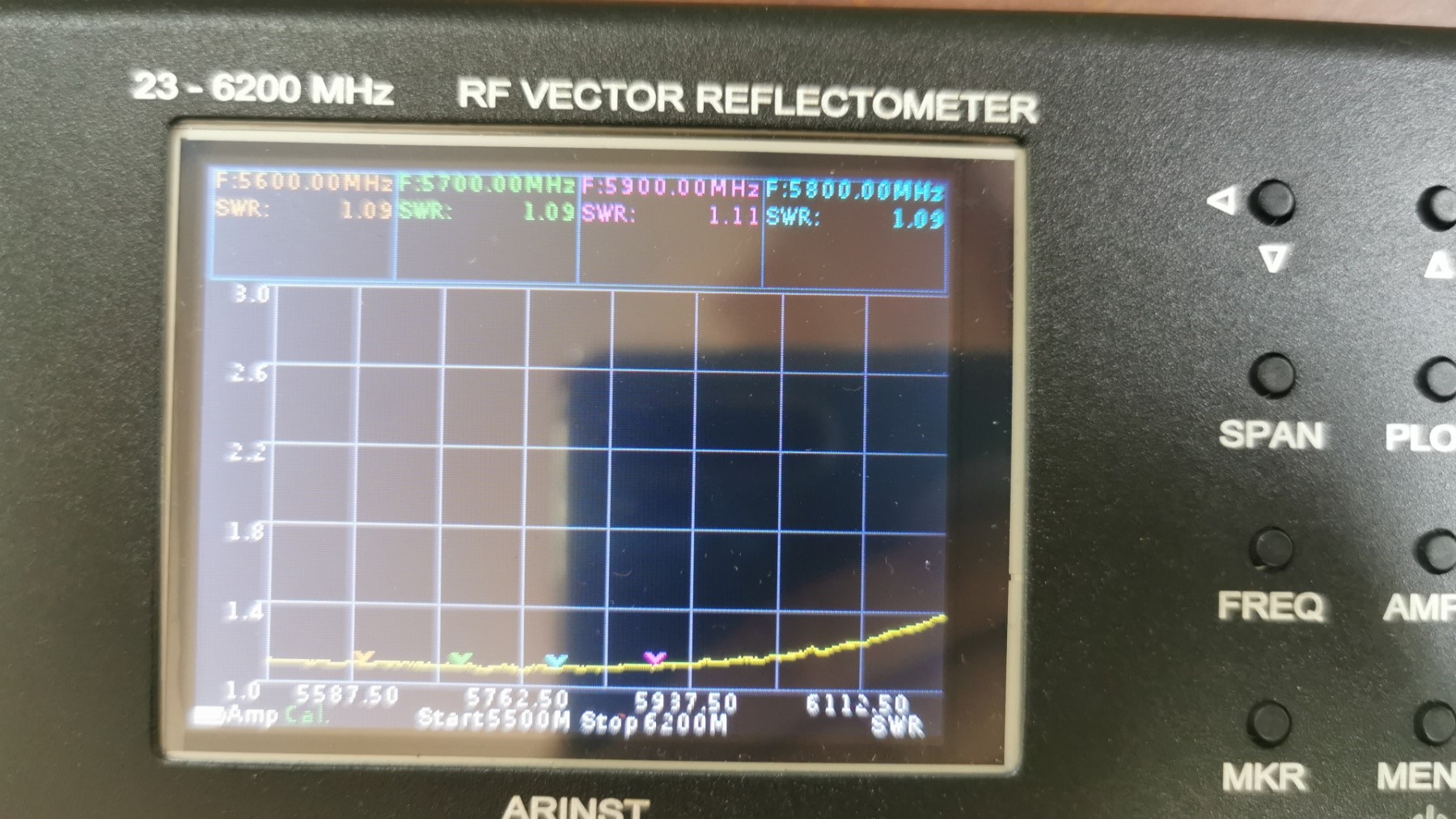
measuring

Radom
 4 people like this
 -
31 minutes ago, clanon said:Petra BB the best (i'll try two of those at 90 and see)
this is not Petra BB, this is Petra 9. this is not a patch, but a slot. it's not mimo. how to place two of these in an 80mm reflector?
if you place two Slot on top of each other, everything will deteriorate and there will be a problem of balancing and branching cables towards the parabola. neither slot nor patch is suitable for direct focus parabolas feed options, except for large mirrors with three arms (1.8-2m).2 people like this -
On 16.09.2021 at 4:58 PM, clanon said:MagnetoElectric Dipole (MED) more bandwidth , less gain and low efficiency on Dielectric ( ALL metal should be better)
PS : and the TUBE DIAMETER doesn't help...either
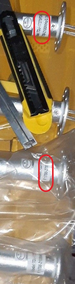
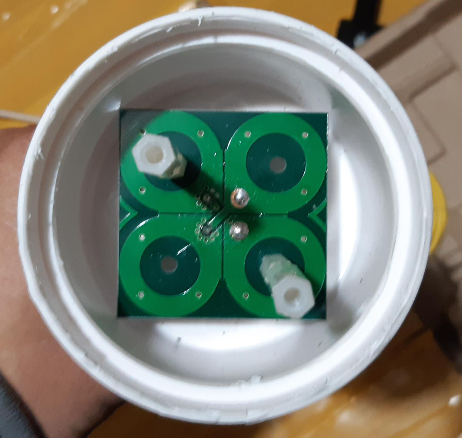
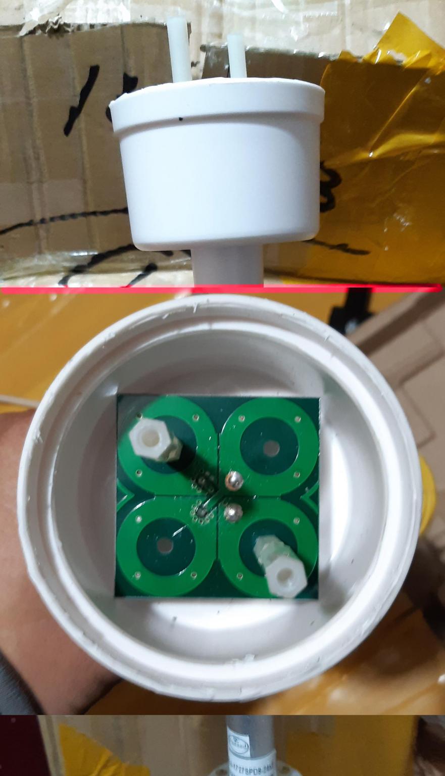
I don't know the design of the patch so that it can cover the 1700-2700 range in MIMO mode with simple powering. With the help of dipoles, this is done easily. IMHO, to expand the strip, you will need another structural element, it is either not shown in the photo, or the dishonest manufacturer did not install it, but PCB racks are used for a reason. For f / D ratios 0.25 to 0.3, you don't need a lot of directivity, 6-8 dBi is enough. the design is quite technologically advanced in production. If you look closely at the photo, you will see the TJD-1727 marking, but the frequencies are different. 1700-2100 and 1700-2700. This is China, only the sticker may differ
at what frequency this design is actually designed without dimensions, it is difficult to say.
 1 person likes this
 -
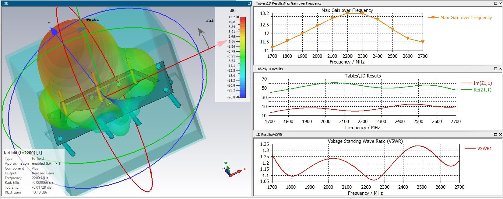
19 hours ago, clanon said:12 to 15 dbi and a nice 50 ohms curve in the whole bandwidth...
show more details on the INFINITE like shape...
so it behaves like 3 half waves SLOTS...?
(wideband)
What happens if that shape is multiplied into a flat BOX...?
(4 , 6 , 8 of those)
Big sizes... 15 dbi ~ 200*200*200 mm
-
Version3


 2 people like this
 -
17 hours ago, clanon said:1mm aluminum
size should be increased X,Y by 10% (1.1)
Dielectric used must be known (Boom and spacers)
impedance close to 50 from 2 to 2.5 ghz
Vswr should be adjusted (exact materials needed and Bandwidth)
"More efficient (NO DIELECTRIC) , a little more gain"
This is a slot-loop antenna. it is not necessary to execute the slowing-down structure on such elements. can be done with wire elements.

 2 people like this
 -
On 04.06.2021 at 0:21 PM, Antenna gun said:please show me how to make them
An approximate model of one element without exact dimensions and optimization.
Only the principle of construction.
 1 person likes this
 -
45 minutes ago, clanon said:all dimensions should be available before buying it , for trial and error
or all sizes are needed before modeling
1 person likes this -
1 hour ago, Admin said:`` Антенна Бестера после Harry36 ...


I'm glad you like my antenna.
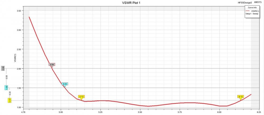
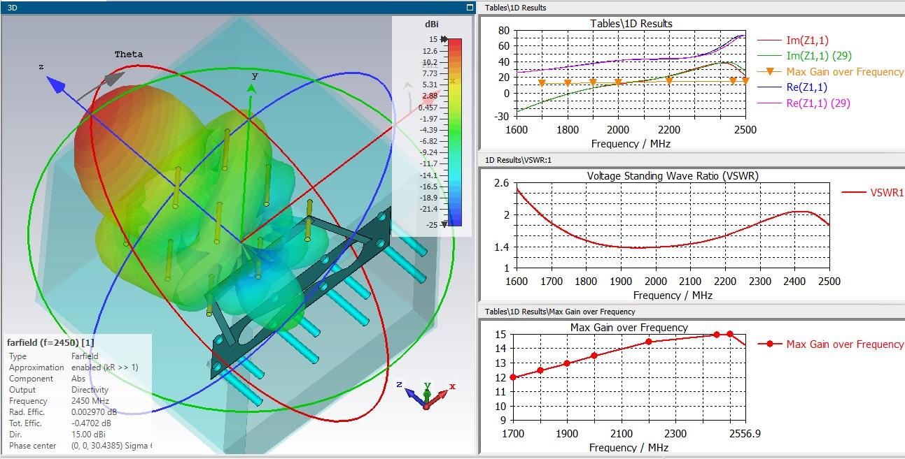
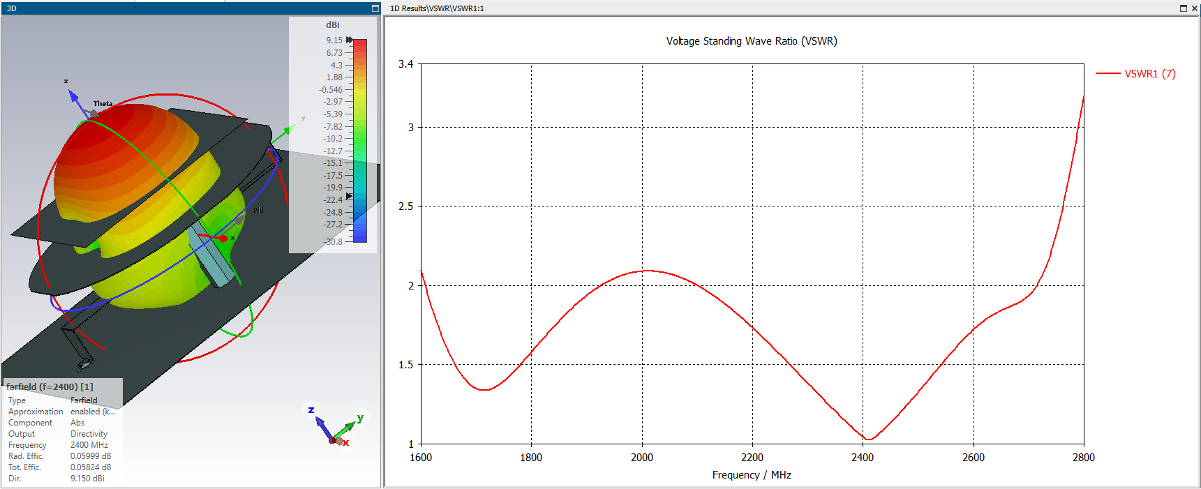
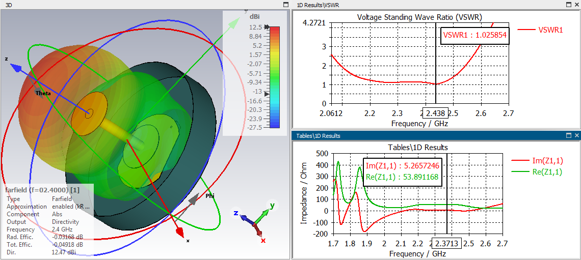
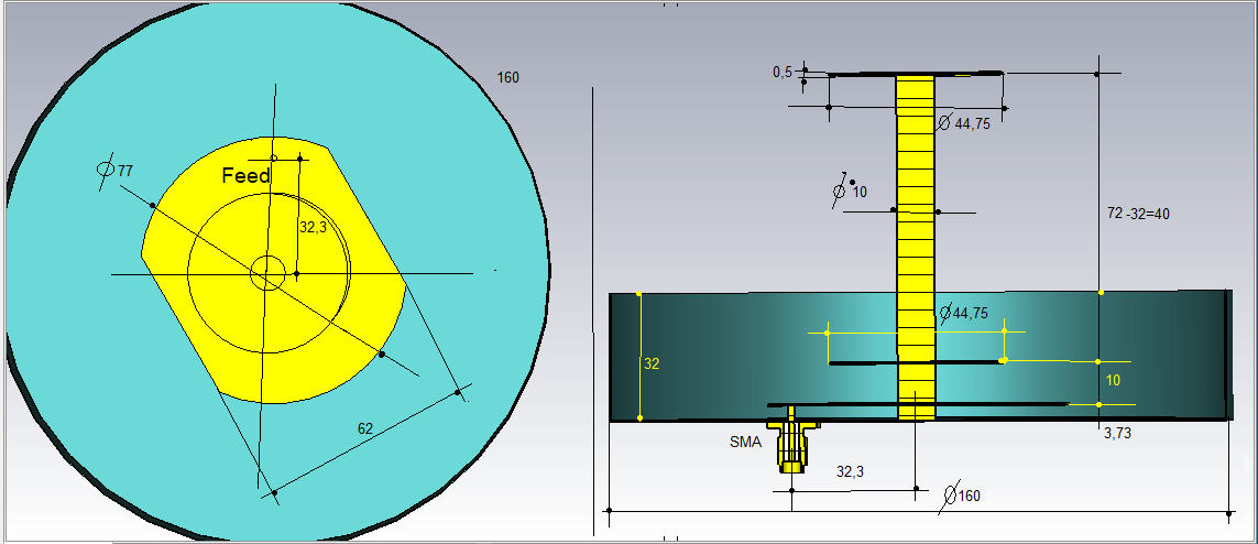
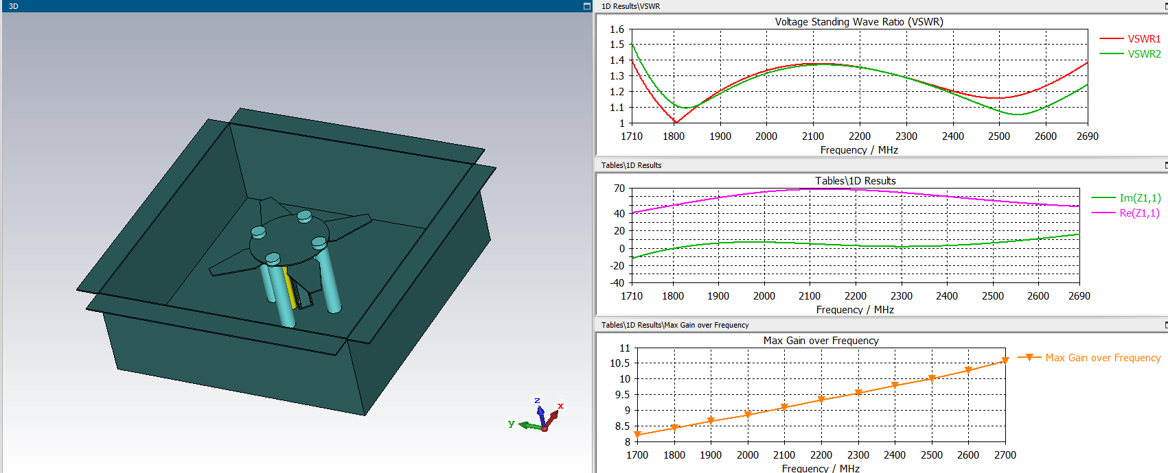
You are wrong with the choice of the disk size. Antenna SWR with optimal dimensions should not exceed 1.15
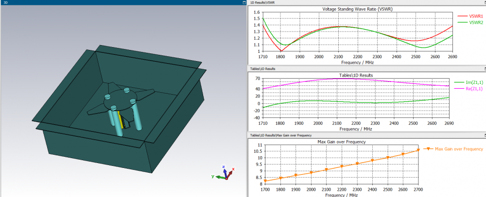
For example, here are two calculations, the first in FD and the second in TD. And in HFSS
-
-
1 hour ago, clanon said: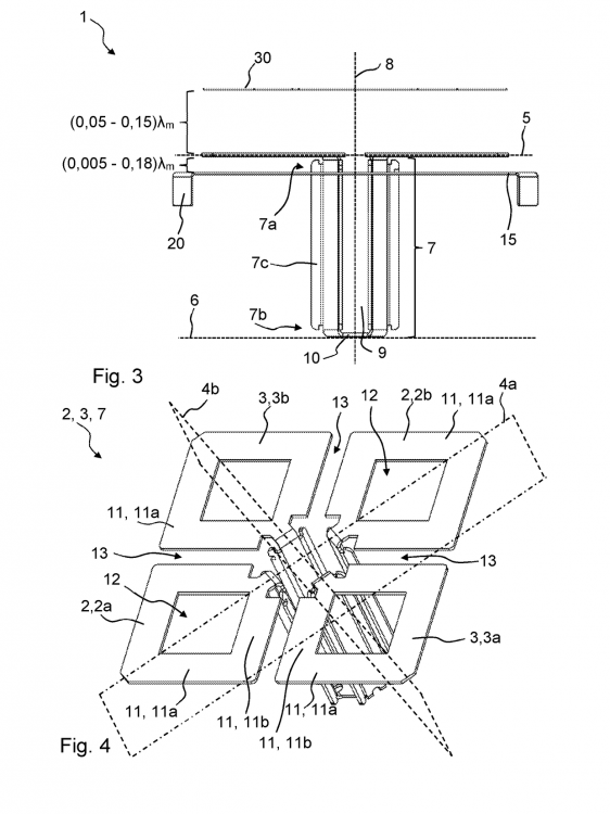
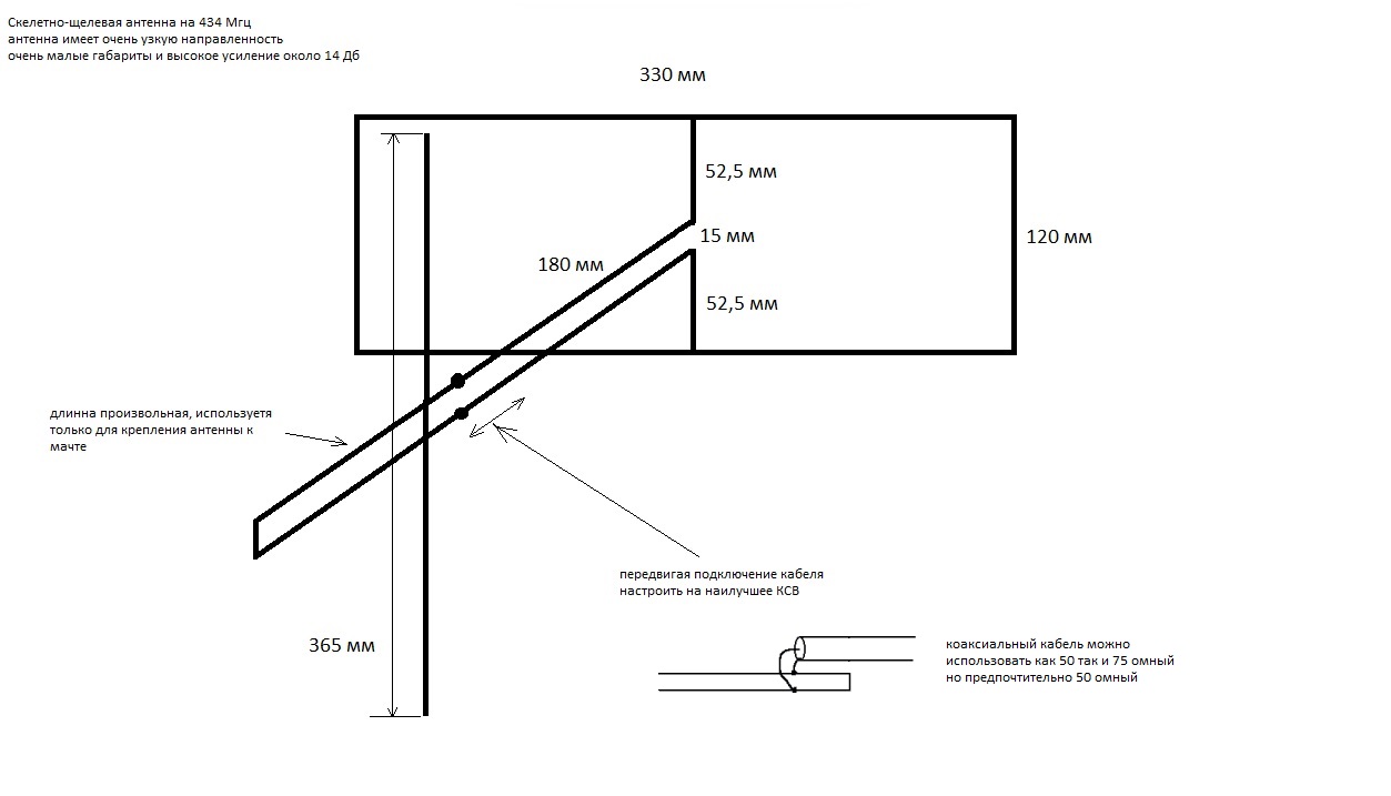
It is very difficult. I came up with a much simpler one. For making with your own hands. Simplicity of design and availability of materials.
Use it.
Newbie, from Russia with love.
 2 people like this
 -
On 12.06.2021 at 10:01 AM, Admin said: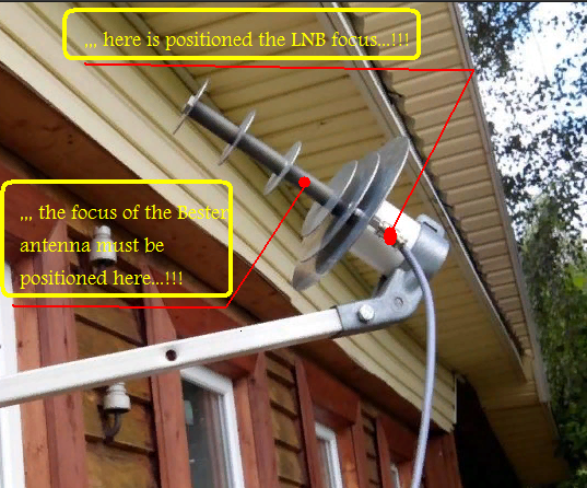
The BDM does not have a focus, but the phase center of the antenna. The phase center of the feed should ideally be in the focus of the parabola. For a higher utilization of the surface of the parabolic mirror, the directivity of the feed should be approximately 10 dBi. Antennas with more or less directivity are less effective as feeds.
2 people like this -
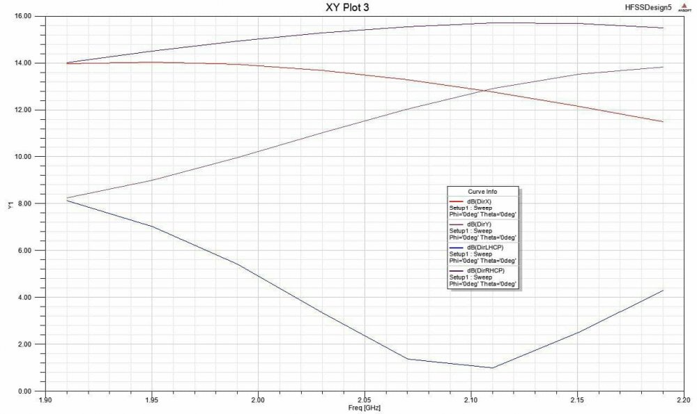
42 minutes ago, clanon said:NEMO i mean
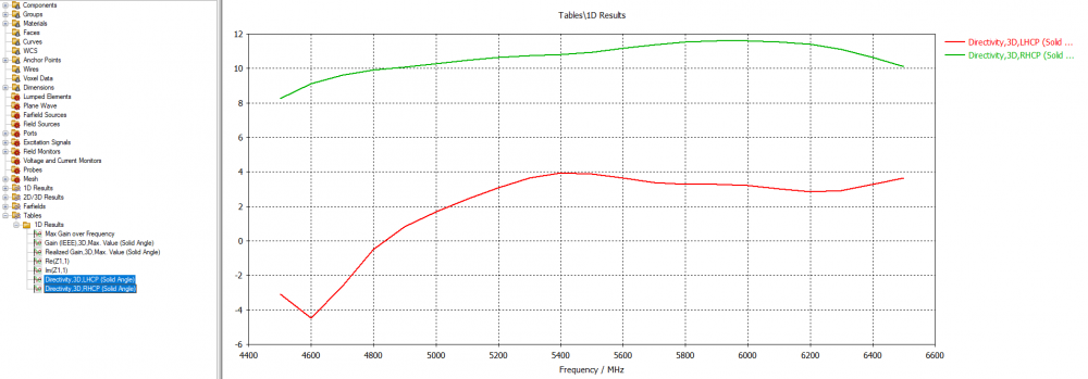
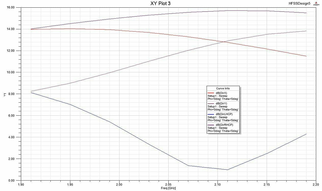
As I understood from dim people, any antenna contains parasitic polarizations. If we are developing RHCP, then we need to get rid of LHCP, if the difference in the LHCP drop (as a parasitic component) differs from RHCP by 10 or more dB, then the antenna has a polarization very close to circular, if about 5-6, then it is close to eleptical , if the values differ by very small values, it is almost linear. I understand from the explanations. For MIMO with circular polarization, this is very important, I think, as well as the parameters of co-polarization and cross-polarization isolation. 2. Antenna slot is a game. This is a different design. Later I will publish the results on Lan and on this forum. The antenna is assembled and tuned.
1 person likes this -
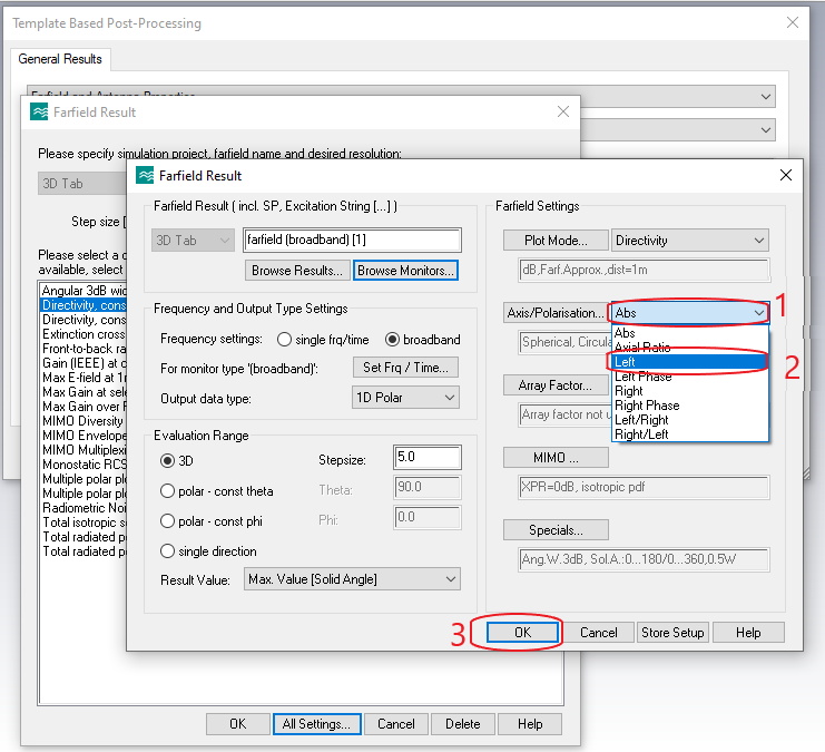
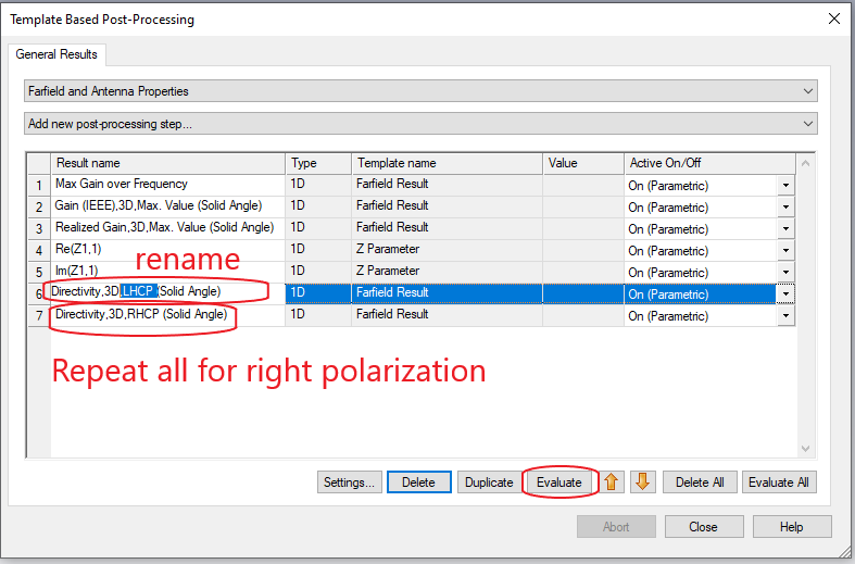
Hello friends! Thanks a lot for the previous answers. As I learn the CST program and start modeling circular / eleptically polarized antennas, I have a few more questions for you:
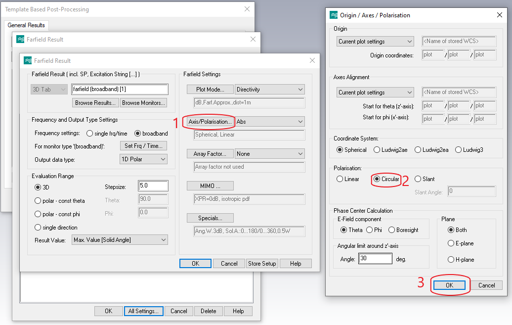
1. I was intuitively able to display the graphs of the left and right polarization components to estimate the eleptics / circle of polarization. I may have been wrong, correct me if I am wrong.

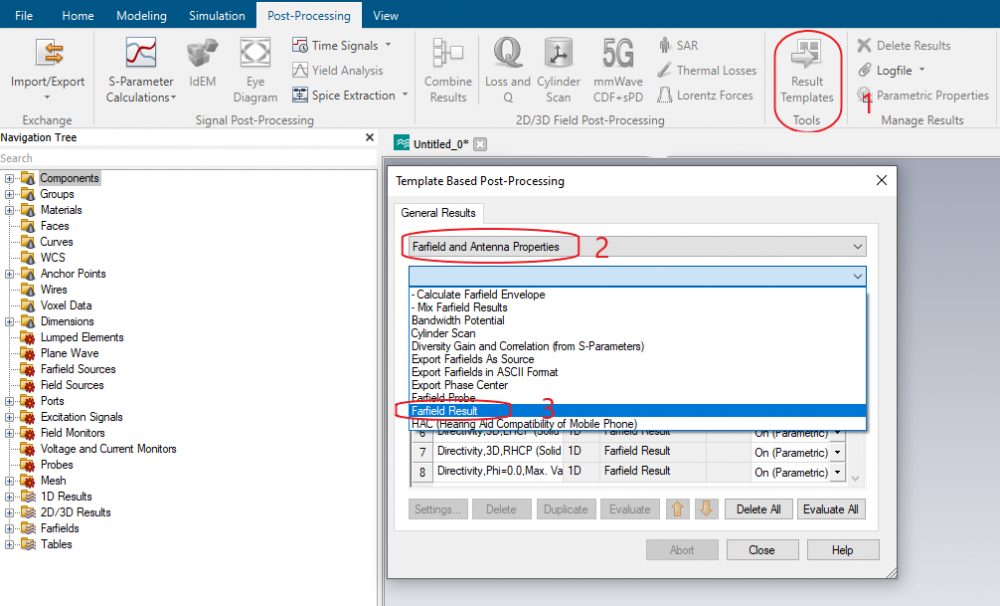
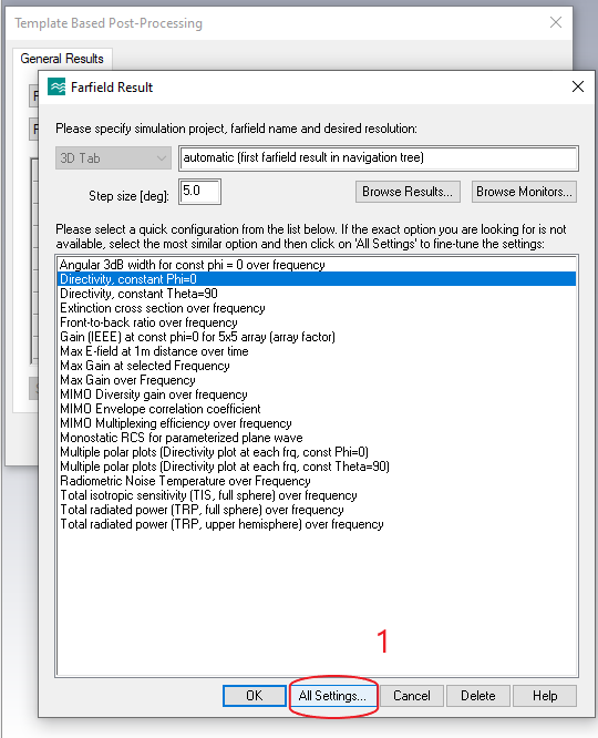
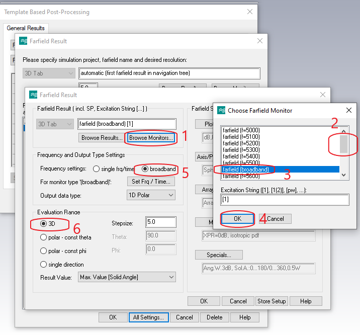
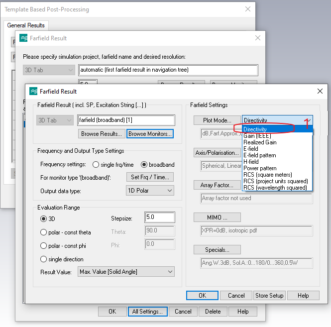

2. The HFSS software package can display graphs in X and Y planes. Is there such a possibility in our wonderful program?
3. if not difficult, show in the screenshots, please.
4. To estimate the isolation between ports in a two-port CPW antenna, it is necessary to estimate, in addition to the parameters S 12 (21), estimates of cross-polarization and co-polarization are likely to be required. Unfortunately, I also haven't found where it can be appreciated.
4. What other parameters need to be controlled when designing circular polarized antennas? Thanks in advance for the detailed answers!
1 person likes this -
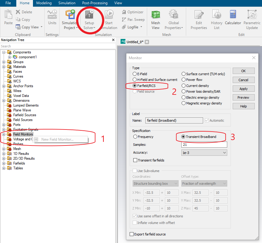
Hi everybody! How to get a picture of the field distribution depending on time or phase? Please respond with screenshots with steps. Thank you in advance.
-
-
1 hour ago, clanon said:SLOT half wavelength radiator...?
Yes, Boss
") 1 hour ago, clanon said:
1 hour ago, clanon said:It would be nice to put 4 or more
thinking of making a grid of 4 butwing? I am confused by the size of this design for such a range: (the size of 4 elements will turn out to be 200 * 200 or more (you need to look at the side lobes), and the gain will be 19 dBi at best.This antenna is already on the verge of rationality (more than a pack of cigarettes). At the beginning of the topic there is a patch in a metal plate, it has a gain of more than 15 dBi
2 hours ago, clanon said:and feed it with a PROBE...
With these dimensions, I have only one idea - SMA on the back of the reflector + balun from a 3-layer PCB (FR4).
What do you say, friend?
1 person likes this -
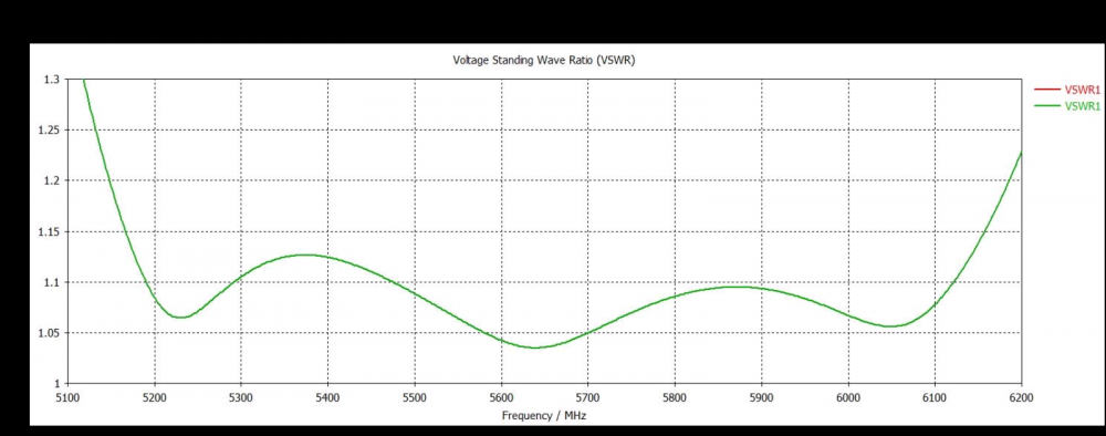
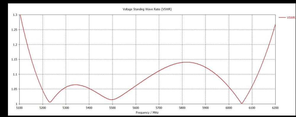
25 minutes ago, Admin said:it is a very good antenna but it should have a wider bandwidth for the 50 Ohm impedance...
This antenna has been modeled for maximum gain, and low VSWR in the 5.6-6 GHz band. real bandwidth by WSWR <2 4000-6200 MHz (5G + WiFi 5 or 6 GHz). You can change the bandwidth in the Simulation -> Frequency section, and also add the rendering frequencies to the History List in the first paragraph by editing it.
1 person likes this -
do you have doubts that they are not true?
-
-
Hi!
cst2021? ок?
1 person likes this
.jpg.dd857bcc31d3fabd719c2e66c1a56219.jpg)


in Antennas 5GHz band
Posted