Register now to gain access to all of our features. Once registered and logged in, you will be able to contribute to this site by submitting your own content or replying to existing content. You'll be able to customize your profile, receive reputation points as a reward for submitting content, while also communicating with other members via your own private inbox, plus much more! This message will be removed once you have signed in.

clanon
Members-
Content count
802 -
Joined
-
Last visited
Posts posted by clanon
-
-
On 24/2/2024 at 4:03 PM, Edel2020 said:It really looks simple....what design to do to get closer to 20db at about 20 km in band 3 1800 MHz?
Wire grill
(big 80 cms at least) OR parabolic dish EVEN BIGGER 1.2 1.5 meters
 1 person likes this
 -
Easier ,for me, if YOU choose ANY 2-3 patches design (10dbi) ( need a frontal picture)
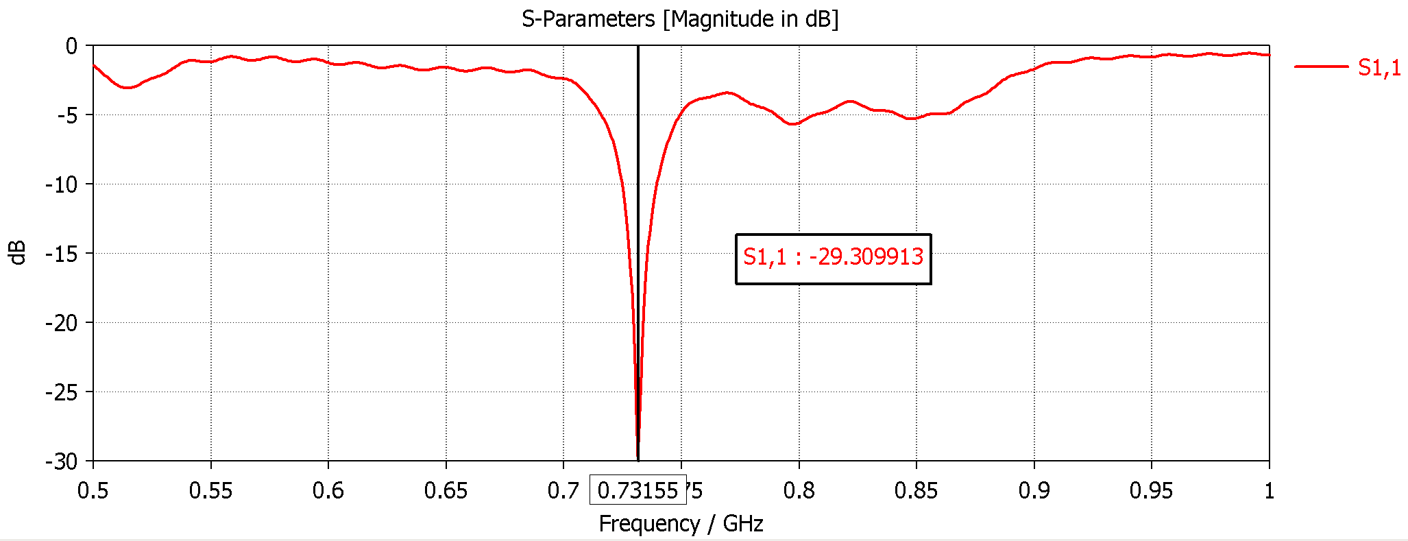
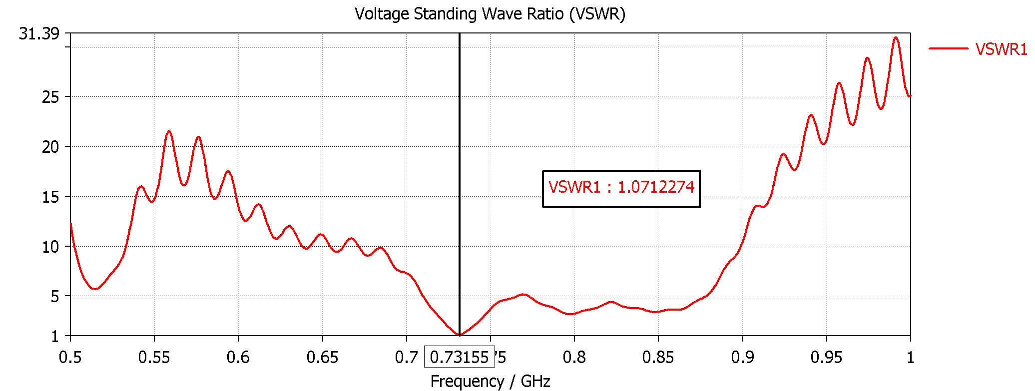
and then we'll make it work at 725mhz...
1 person likes this -
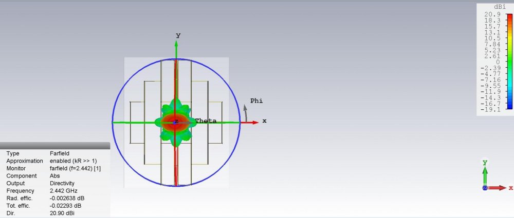
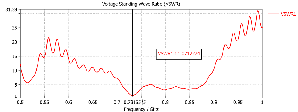
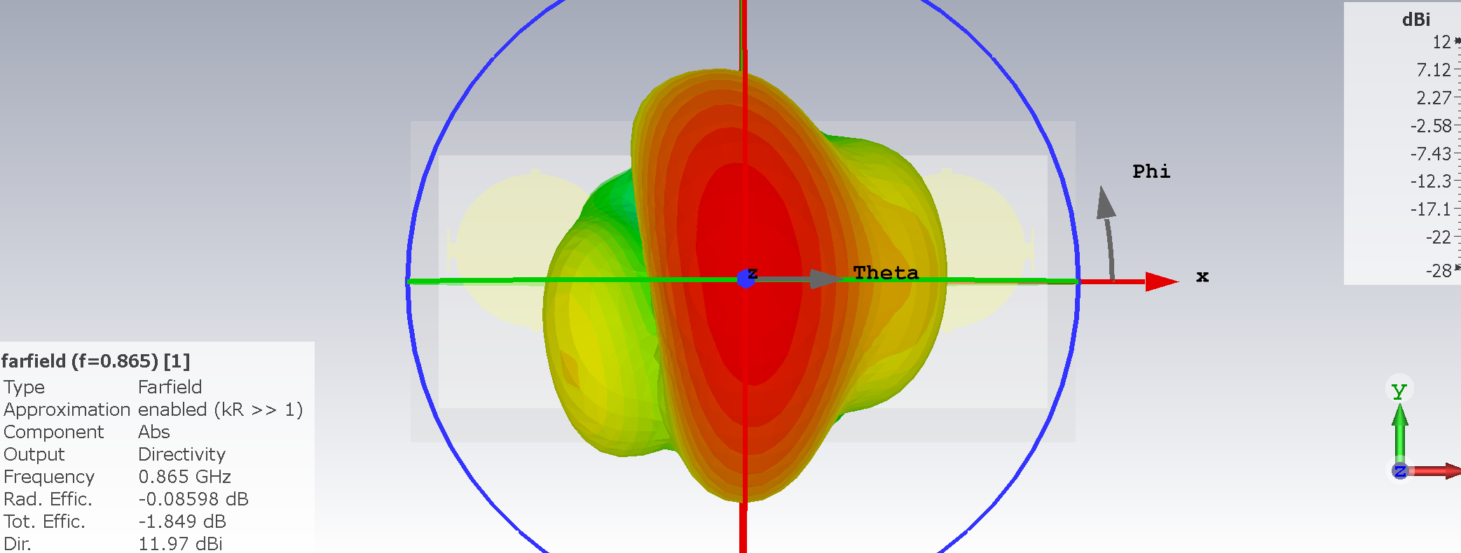
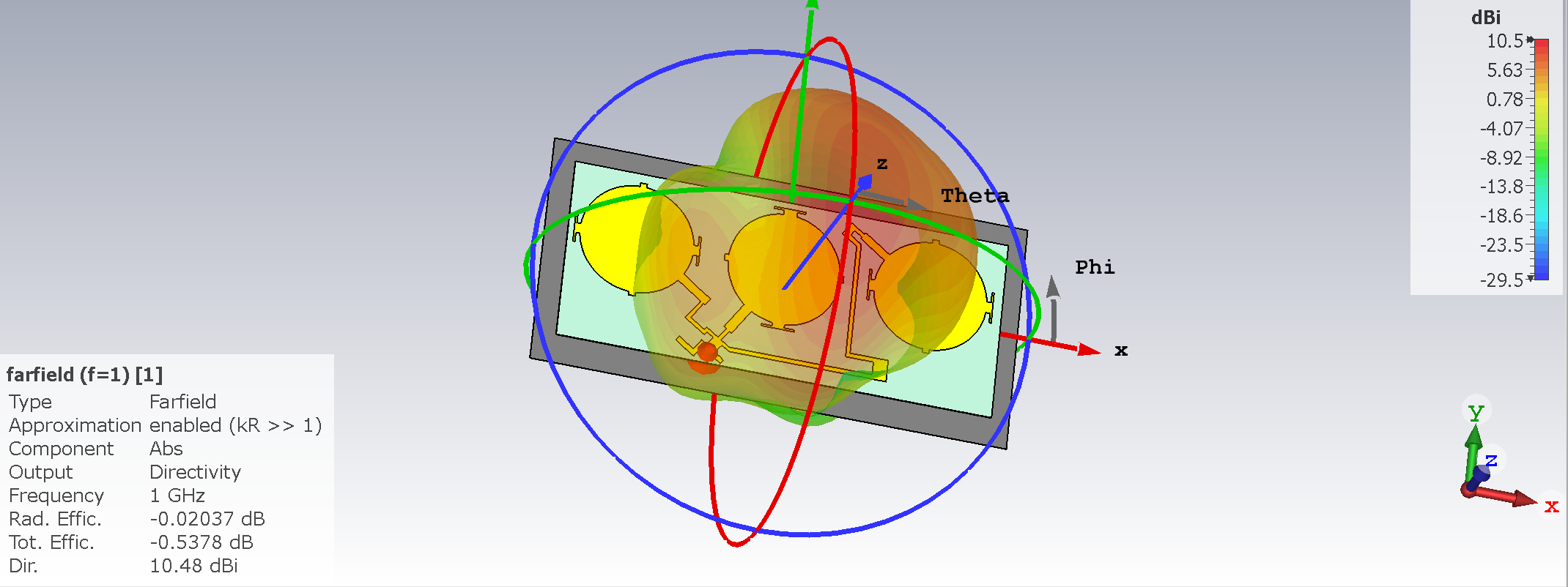
Easily 12 dbi at 725 mhz
-
-
Could be made to ANY frequency , Circular pol (could be made lineal easy) efficiency could be better NOT using FR...

-
On 23/12/2023 at 9:00 PM, eco32 said:{,,,this construction is a bit wrong, mcNeill doesn't really do good things...!!!}
McNeil, He performs titanic antsy work in making phantoms, but do not fully understand it, for example, phase shifters are called load coil, and so on and so on...
{,,,on this forum there is such a dipole in the correct construction...!!!!}
HAMs do not know it, I have not yet seen any HAMs construction with the use of this type of matcher/balun. Most popular is this one:
This is material for a separate topic, LTE/Wifi antennas rarely have a balun.
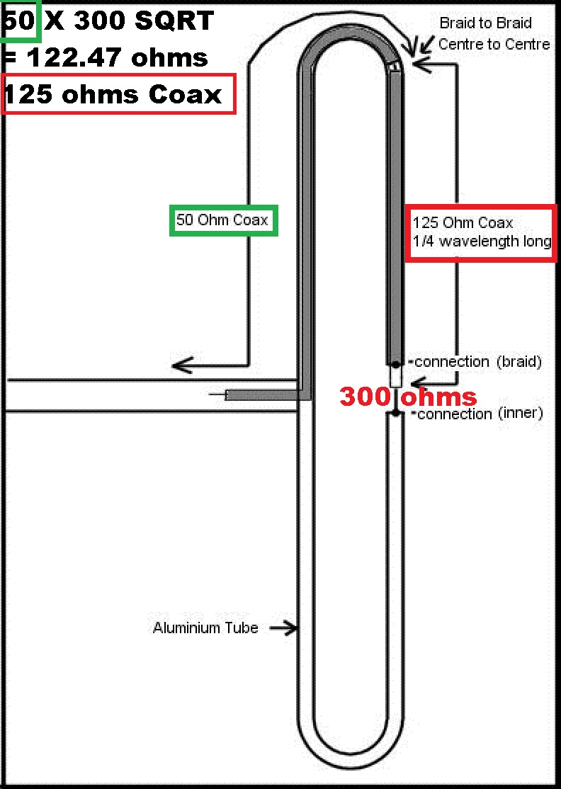
4:1 balun (50 ohms to 200 ohms , 75 ohm to 300 ohms , etc)
2 people like this -
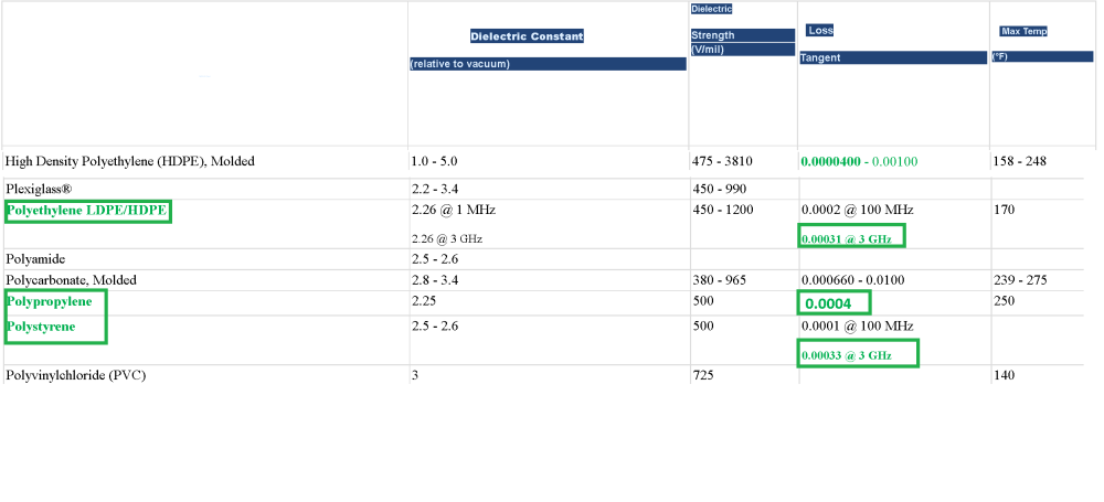
Correct adaptation from 50 ohms to 300 ohms antenna (Quarter wave long should take velocity factor of Coax in length ) 0.66 PET , etc

-
On 4/12/2023 at 4:43 PM, Edel2020 said:How much loss will the published model have?
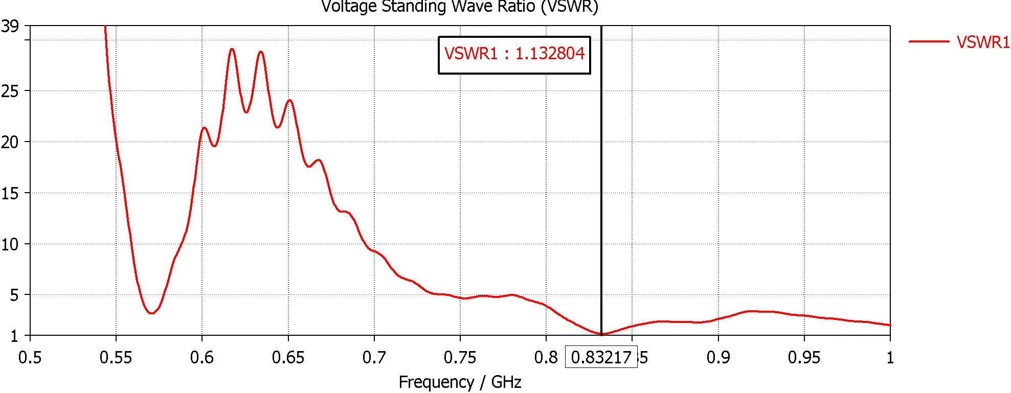
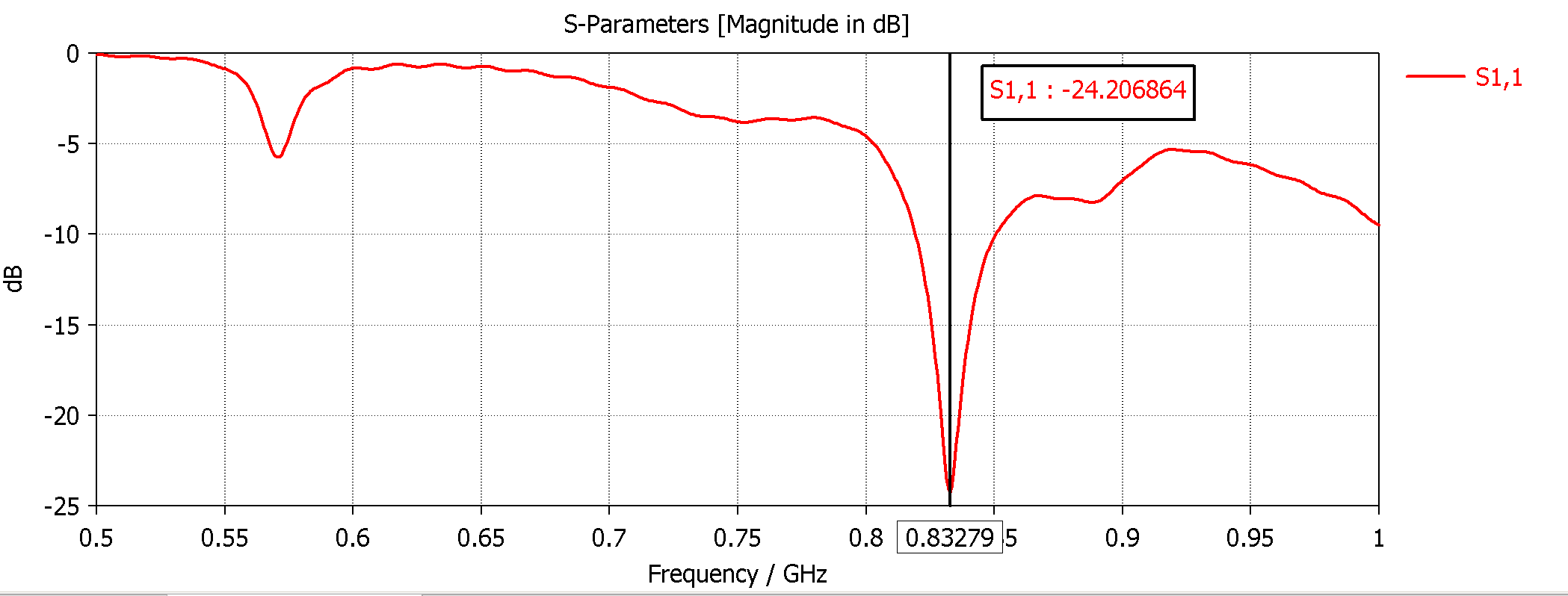
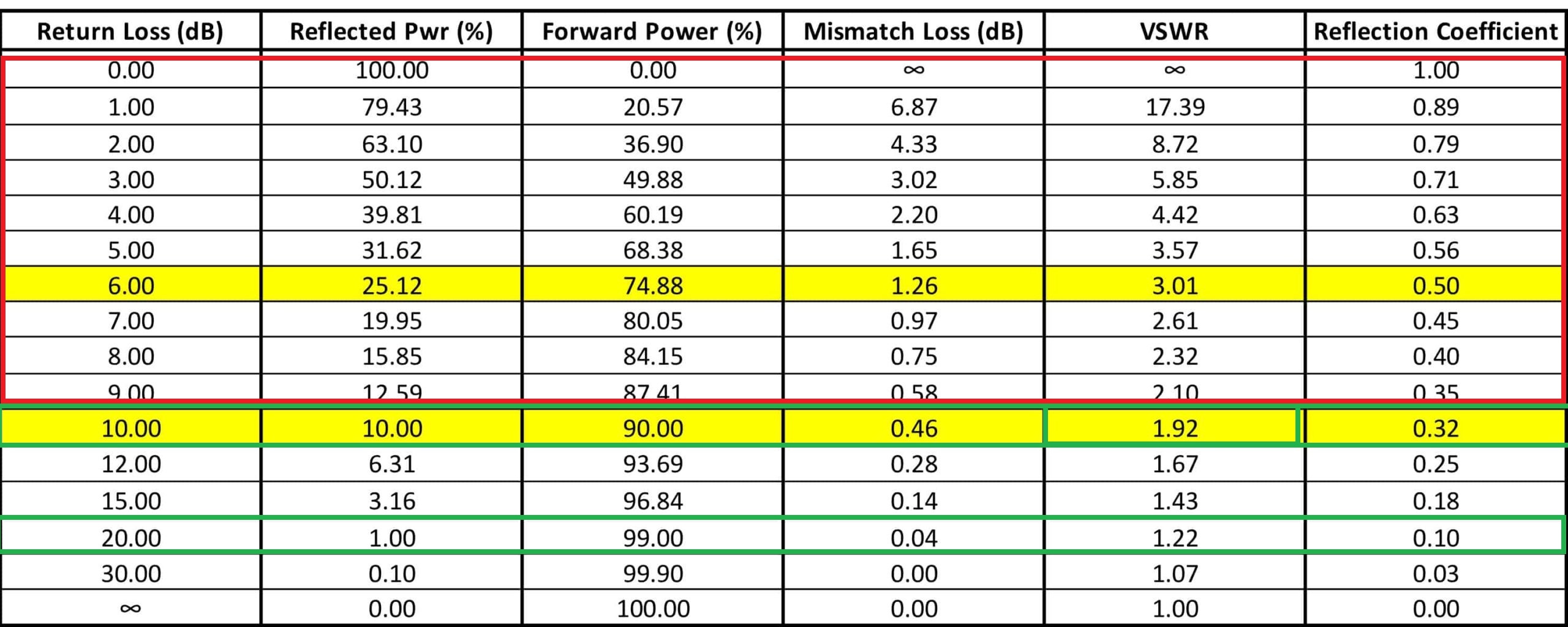
a Ratio between antenna Impedance and radio impedance the bigger the difference bigger the losses...let's sat 300 ohm antena/ 75 ohm radio 4:1 VSWR = close to 40% reflected power on TX...on RX it's gonna be WORSE...(small signal)

-
On 17/11/2022 at 10:05 AM, vova.gumerov said:Hello Jomy! I hope everything is fine with you. And we have a disaster ....... To make such antennas, you need a 3D cutter! Such things are not done with scissors and a grinder!
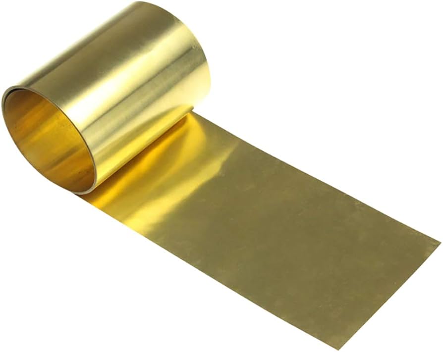
0.2 0.3 BRASS paper...? and a sharp cutter...several tries (using a printed PAPER taped on top) cut through the printed lines...?
solder the vertical strips...
PS: 0.2 is pretty RIGID...
-
Yagis hit a WALL at 15 dbi most of the times (with 15 elements and a BIG reflector)...you need 2 for 18 dbi , 4 for 21 , etc
-
-
-
On 29/11/2023 at 7:15 PM, eco32 said:No one did it with biquad
nope...BUT those complex feed networks steal gain (several db)
-
double post
-
Water absorption should be adressed in PES foam...Changes ALL.
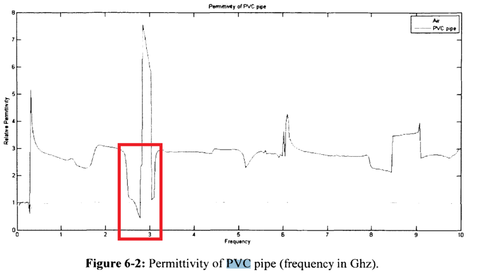
PVC pipe has THIS weirdness...
-
12 hours ago, eco32 said:once again:
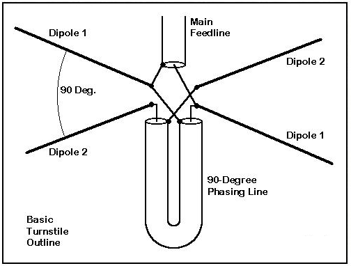
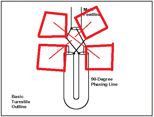
Dipole has oposit phase on the arms, biquad has same phase on the both ends, trick with phase shiter will not work here.
LOOP should be CLOSED at feeding Points...
then , EACH Loop should be feed with 90 degrees phase difference
 2 people like this
 -
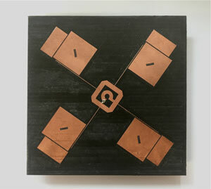
Double lineal here , NOT circular "The polarization of the emitted signal depends on the spatial location of the antenna. Horizontal - horizontal, vertical - vertical polarization. [4] The horizontal position represents when both squares are next to each other, the vertical position is when both squares are placed one above the other."
DoubleBiquadOmni-Antennafor2.4GHzWirelessLinkApplication.pdf
-
On 11/23/2023 at 0:26 PM, eco32 said:Yes, Thank You!!!, it looks like his cross biquad/biloop has 8dBi isted of 10dB from single biquod, without e-field chart it's hard to tell if it's circular polarization in this design there are no phase shifters. In my opinion it has linear polatisation. (I don't have to be right, maybe there is something going on there that I have no idea about)
Just only for Example: S-band circularly polarized crossed dipole antenna for automotive applications
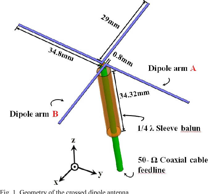
YES you treat it like a simple dipole (but polarization is 180 degrees inverted for a double quad)
Then to get Circular Polarization , you need to retard 90 degrees the wave at each quarter making a 0 90 180 270 rotation (for this the easiest approach is a Quarter wave length (dielectric in coax included) from One biquad to the other...
-
On 20/11/2023 at 6:41 PM, eco32 said:Add to previous post:
I know that it is possible with dipoles, because there is an opposition phase on the "arms", I have no idea how to do it with a biquad, it has same phase on opostit cornersit should be possible with a 90 degrees (velocity factor of coax x 1/4 wavelength) between both antennas (but interactions should be simulated)...
1 person likes this -
one of the LOWEST in the world 0.0003 at 3000 mhz , only one better Polypropylene...at higher frequencies...5.8 ghz ideal...
-
On 3/11/2023 at 3:40 PM, Admin said:,,,but if galvanized sheet and wire supply lines are used....???
I would give it a go ...BUT with circular patches...we'll see...(you had one like that YEARS ago... mimo...remember...
1 person likes this -
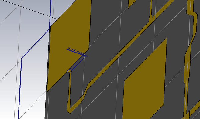
yup...5.84 cm by 5.4 cm...(these are HIGHLY related to the Dielectric Factor , change from 0,4 to 0,5 would change several millimeters these dimensions)
-
it would be interesting...could be Laser cut or stamped...Wires have more REACTIVITY (Imaginary Z) Inductive reactance...impedance curve is always smaller...2mm copper ...maybe...
Copper tape is easy to cut with cutter under print drawing taped on top...perfect
you get more losses in the metal distances should stay the same and sizes...
to keep a good Impedance and low 2 mm or LESS from reflector the Feed network
Patches 4 mm or more from reflector (there is a step of 2 mm)
 1 person likes this
 -


in Antennas for 2.4 GHz band
Posted
yeah , it's easy with the model....pretty sure you are gonna end close to 1 meter by 60 cm or more GRILL...