Register now to gain access to all of our features. Once registered and logged in, you will be able to contribute to this site by submitting your own content or replying to existing content. You'll be able to customize your profile, receive reputation points as a reward for submitting content, while also communicating with other members via your own private inbox, plus much more! This message will be removed once you have signed in.

clanon
Members-
Content count
678 -
Joined
-
Last visited
Posts posted by clanon
-
-
Those are 2T2R (mimo) they NEED both antennas to make FULL use of BANDWIDTH
sensitivity is better on the 841 (need less gain and power)....
Link budget calculates at least 18 dbi gain needed for 17 18 dbm of power and -68dbm sensitivity...
1 person likes this -
Line of SIGHT or OBSTACLES , if so , what kind of obstacles ,
Height you could use , mastil tower...
Radio types (router extender power , sensibility)
THEN and only then , you know how much gain you'll need...imho
1 person likes this -
Jomy try making it a LFA , doing an HORIZONTAL folded dipole , you can make it 50 ohms by that change and dimensions , the rest stays the same (director reflectors)
-
wire is SO reactive...
-
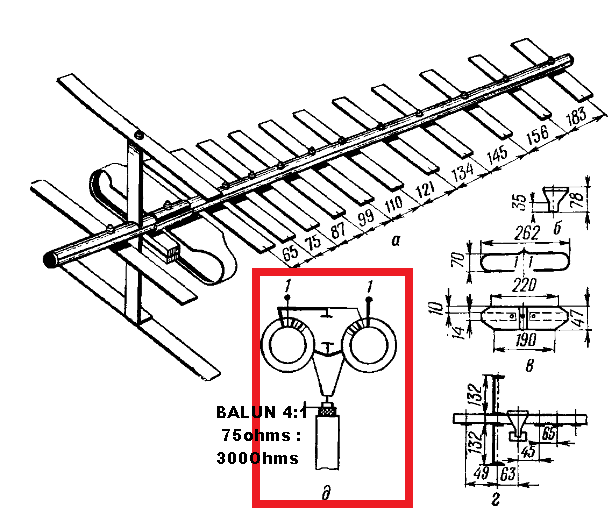
it should be studied and simulated , since impedance 200 ohms (originally) will be 100 ohms for two ...but 4 of those would make a direct adaptation to 50 ohms (1:1 balun required)
and YES
-
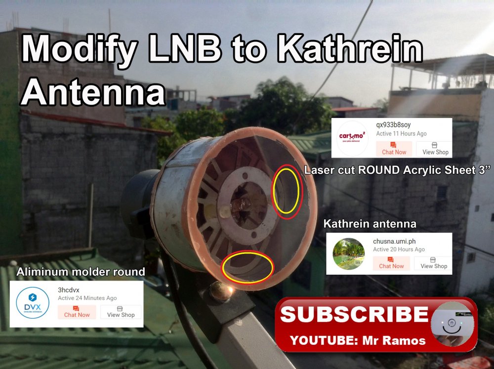
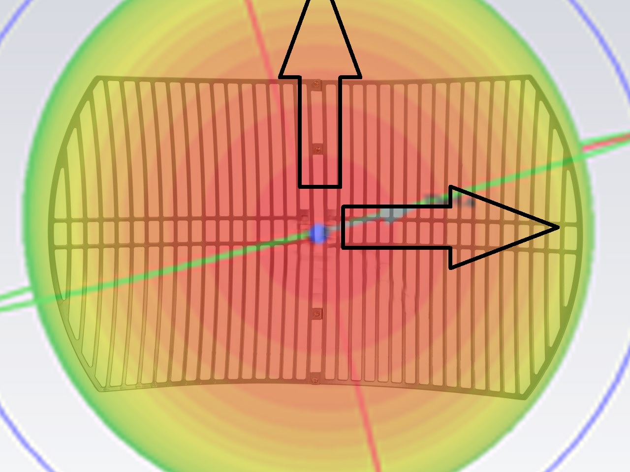
shabra , what swarg is saying (i think) is that you should MAKE sure that the base of the MED sees a GND (center of grid) at the SAME point like in the BASE station (telecom antenna) which means HOLDING it from OUTSIDE and BEHIND with the circle (director) pointing in to the GRID...
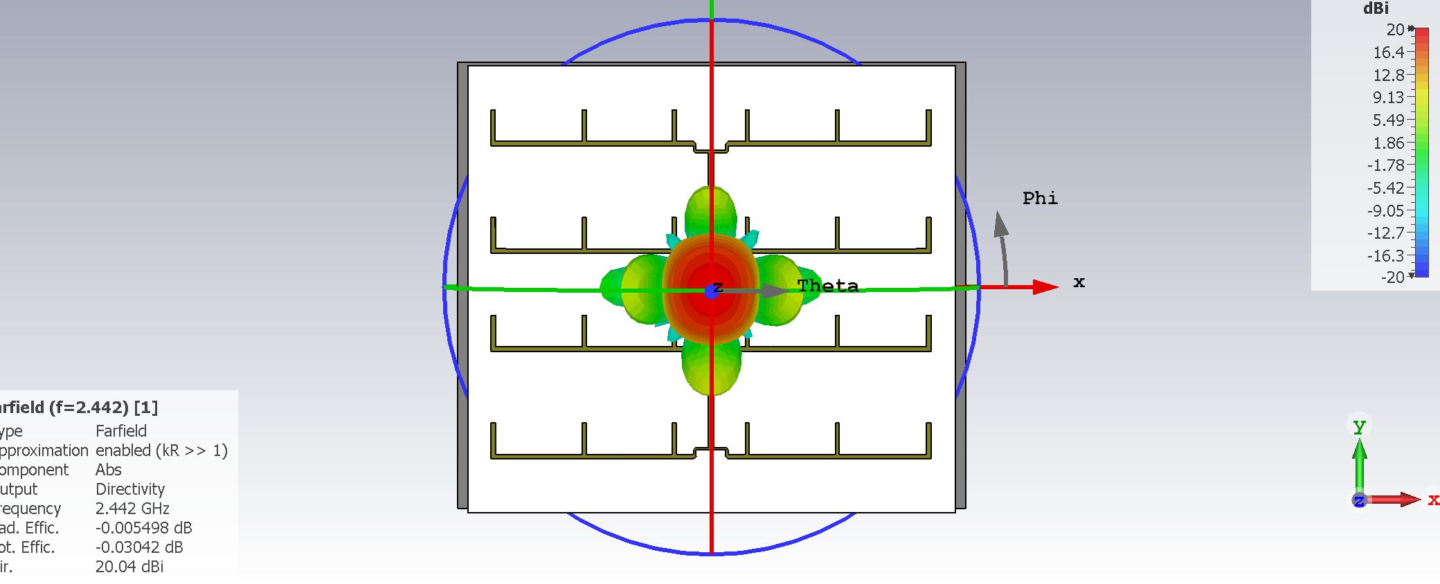
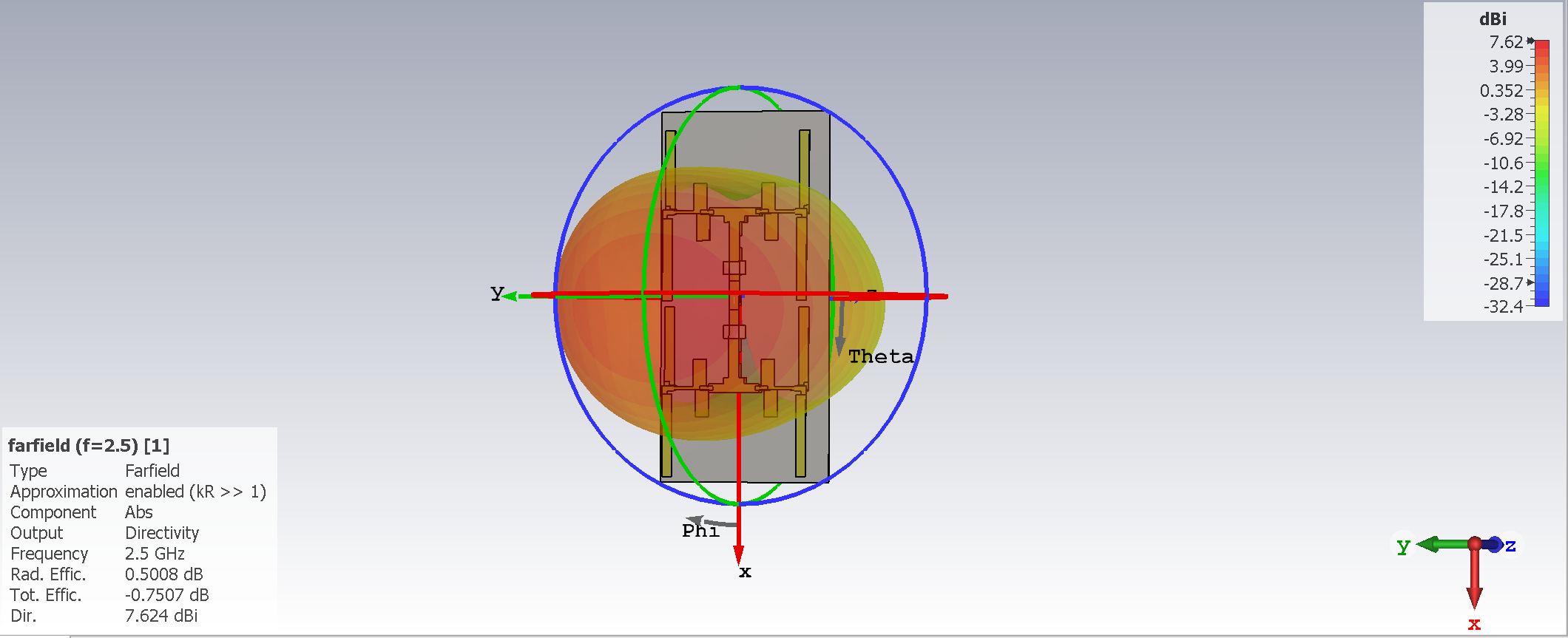
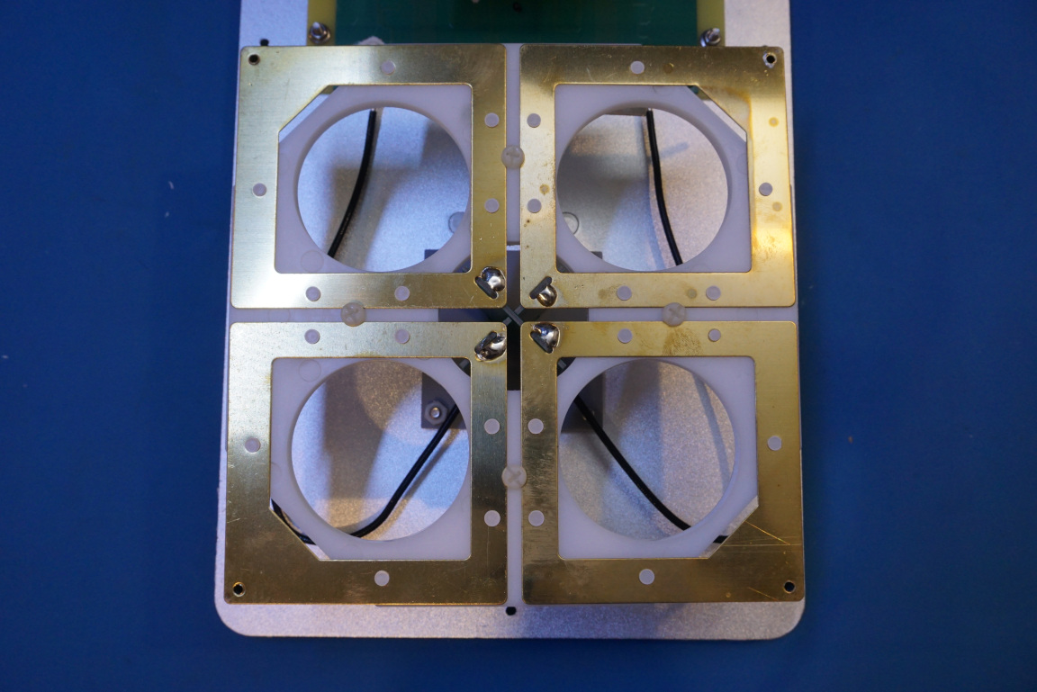
And that the lobe of this MED is FAT and goes in two directions (polarizations) meaning that you are spilling some radiation since your reflector (grid) is almost rectangular (Circular would be better to reflect both dipoles) which are at 90 degrees
 2 people like this
 -
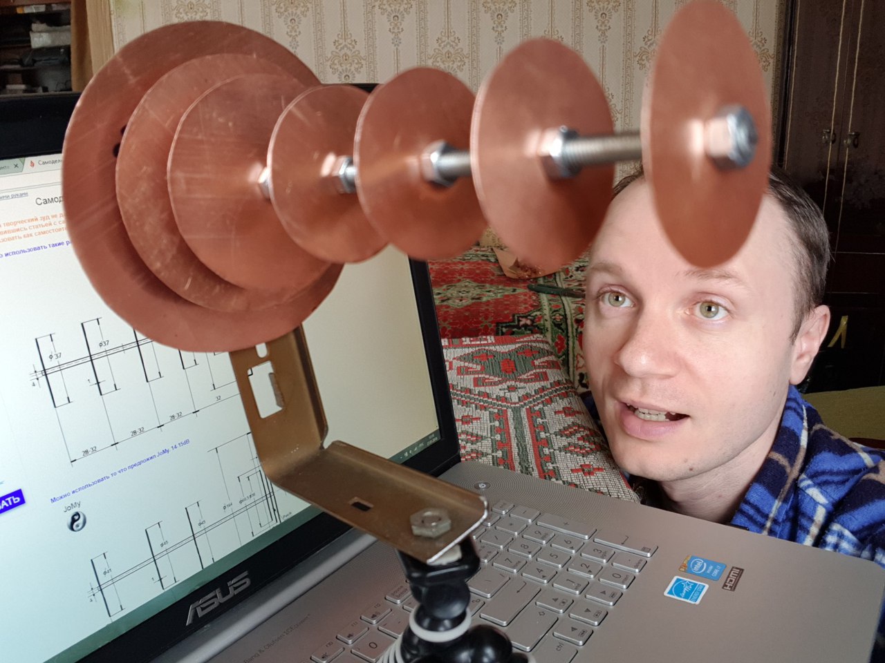
On 12/4/2018 at 3:23 PM, Admin said:From here,,,http://give-all.biz/articles/samdel/samodelnaya-antenna-analog-obluchatelya-bester
These are my drawings...!!!!

HEY JOMY did he say THANKZ or named you...?
1 person likes this -
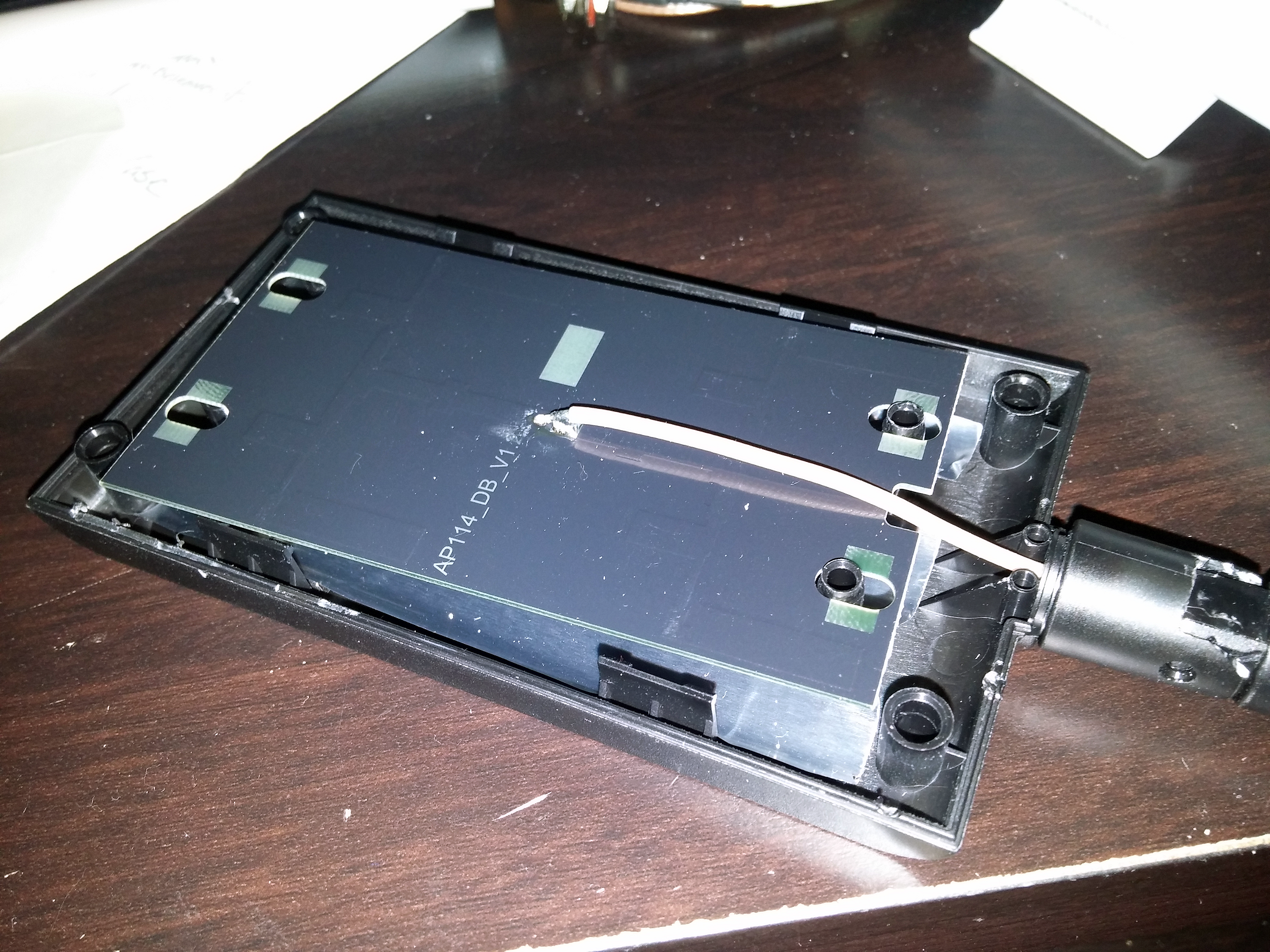
if TOLERANCES (diameters on shield , leads , PCBs) are not maintained , impedance would change. I would solder straight from modem , card to antenna , if possible. Keeping distances as short as possible and impedance (cable shape ,curves) as minimum as possible. ALL connectors have loses imho
2 people like this -
HUMIDITY and MOISTURE inside COAXIAL cable could be a problem...there. over time. a layer of some insulation or cover all in thin PET (nylon) dielectric paint could be better...
Cable changes inside due to WATER and you lose SIGNAL
1 person likes this -
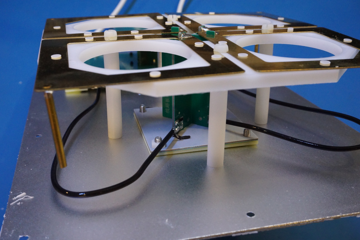
DISTANCE to REFLECTOR must be TAILORED to local needs...(FR4 quality . reflector enclosure sizes and shapes) but it's on ballpark...i think

-
 1 person likes this
 -
On 24/11/2021 at 9:59 PM, Shabra said:It work in 2100 mhz
focus point is important (distance to reflector) some mm make a huge difference...
did you try with antenna (reflector ) at 90 degrees...VERTICAL...?
2 people like this -
26 minutes ago, Harry36 said:Unfortunately, without the exact dimensions (although I do not see any differences from the original), I do not presume to judge the frequency range, perhaps the reduction of the reflector and the plastic case with the rod played a role. But we all see the fact of theft without the slightest alteration with our own eyes. This is a very sad page in the history of the company.
i catched Mikrotik stealing BUT developing over the theft here
-
easier to STEAL than develop-invent...
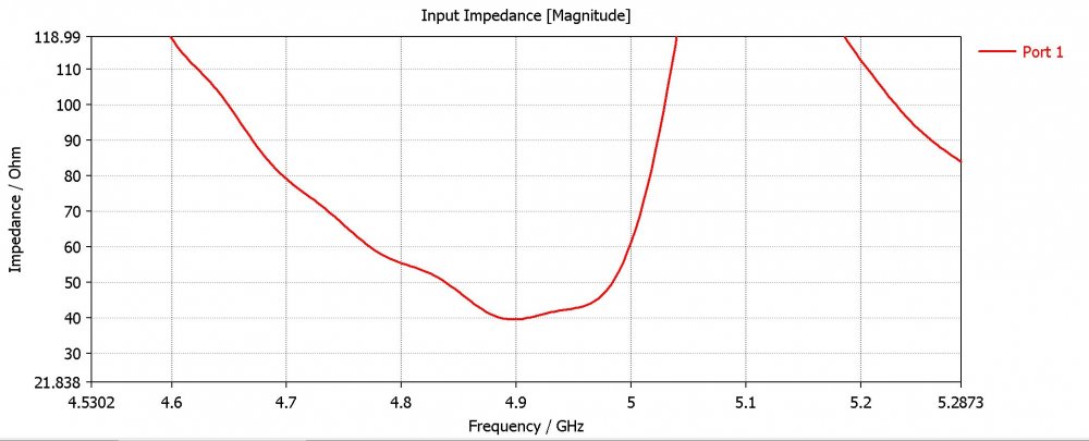
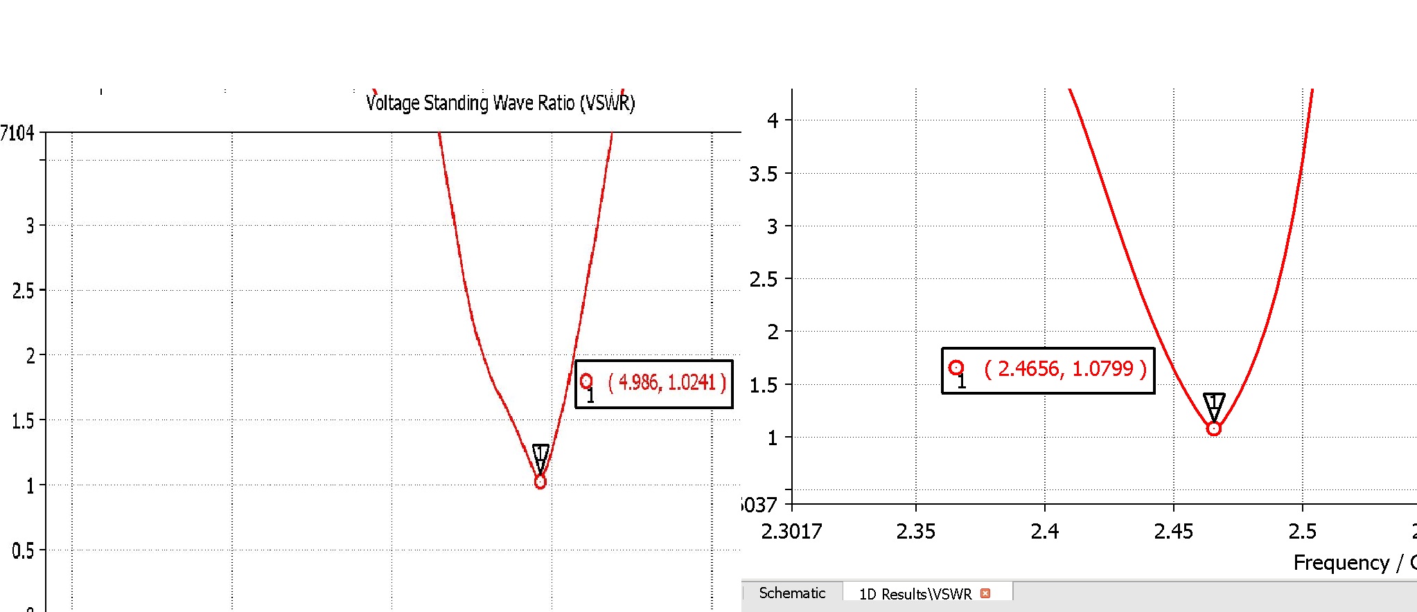
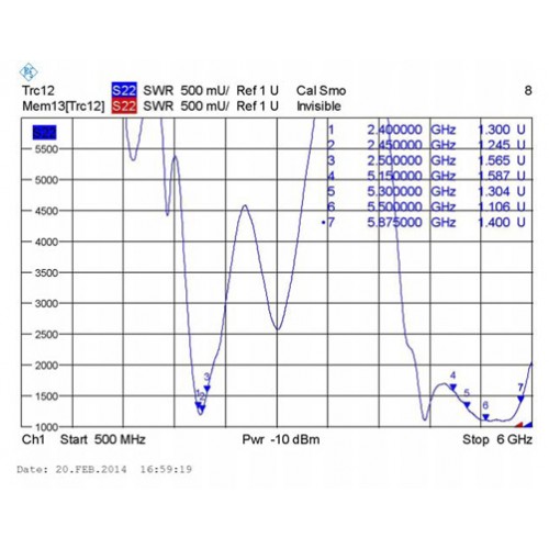
nice bandwidth... could it be SHIFTED to 1 ghz (LTE)...? Who needs 3,5ghz...
 1 person likes this
 -
-
That TRENDNET is easier to build and simulate...
wouldn't be GREAT to develop an ARRAY bi-band using dipoles...? (15 or more dbi)
-
Couldn't find any...(searching , i'm trying)
Working on IMPEDANCE adapting...
 1 person likes this
 -
1 person likes this -
 4 people like this
 -
-
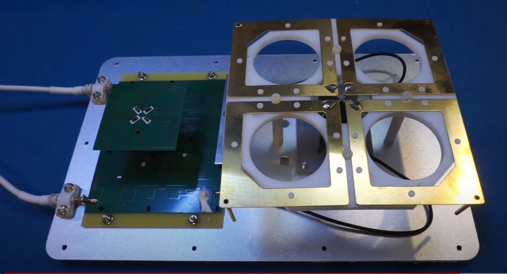
Up to 9 dBi gain between 1710 and 2700 MHz, and 6 dBi gain between 600 MHz and 900 MHz.
+/- 45 degreee cross-polarization.
https://www.youtube.com/watch?v=vm4hV1ITrp0
 1 person likes this
 -
-
SQUARE works too (aluminum plate RIVETED)...leave at least 1 cm to dipole borders...(my GUESS)
1 person likes this -
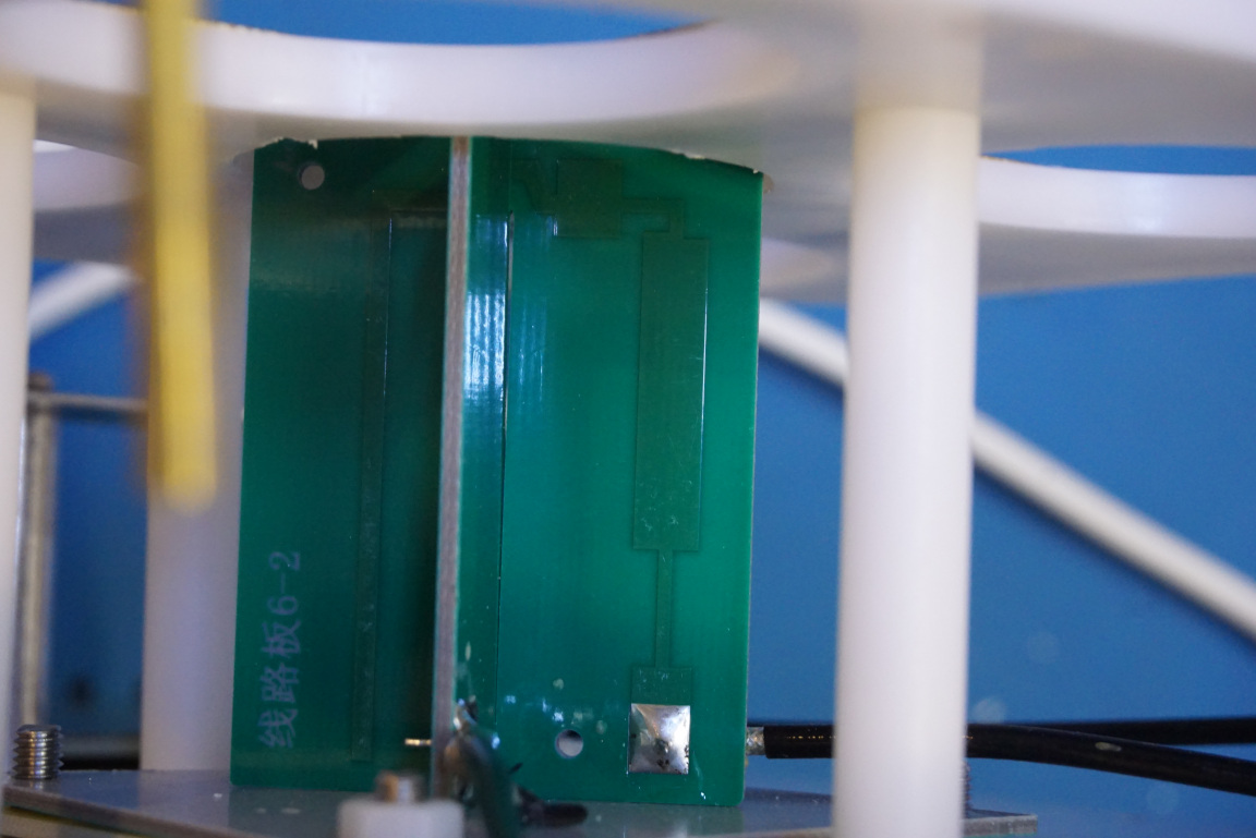
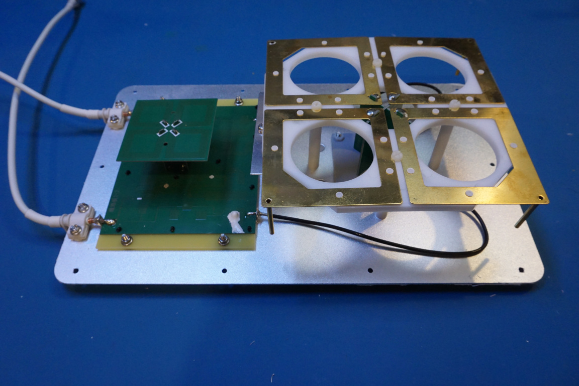
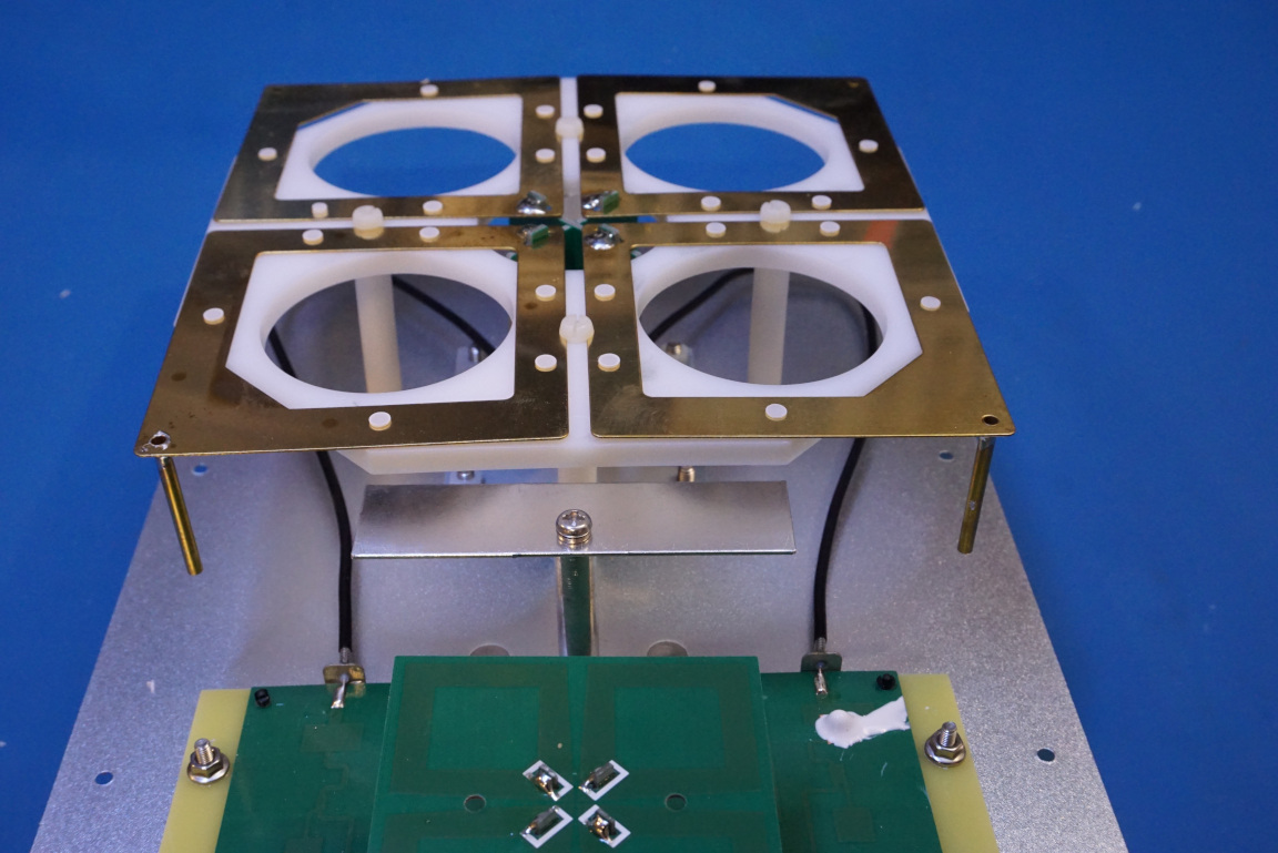
The DIAMETER of the container ...is too small (dipoles are leaning-contact with container) apparently...(Which would give a jumping signal as it is seen , high and low swr , s11, impedance and changing diagram of radiation)
 1 person likes this


in Antennas for 2.4 GHz band
Posted
if you choose parabolic dish reflector
you'll need
any good TWO PORTS feed for that dish (mimo 2Tx2Rx REQUIRES two cables , two antennas or one at 90 degrees between two ports) to get FULL SPEED it maight work okay with just ONE cable-port but NOT FULL SPEED (depends on HOW it was configured , firmware settings)