Register now to gain access to all of our features. Once registered and logged in, you will be able to contribute to this site by submitting your own content or replying to existing content. You'll be able to customize your profile, receive reputation points as a reward for submitting content, while also communicating with other members via your own private inbox, plus much more! This message will be removed once you have signed in.

clanon
Members-
Content count
844 -
Joined
-
Last visited
Posts posted by clanon
-
-
3 hours ago, Jayakumaran S said:I noticed the simulation includes a connector. Is it necessary to simulate with one?
Also, if the antenna ends with a copper rod, I have assigned the wave port by selecting the rod’s end face. Similarly, for a copper tube, I selected the tube’s face and assigned the wave port.
Kindly confirm if this method is correct.
Face select inner+pet+shield+outer edge , then assign wave port (ALL of them should be leveled)
puting a PORT on the END of an ANTENNA is a NO-NO
1 person likes this -
18 minutes ago, Jayakumaran S said:could you please send this corrected design file.
And where i can see the OHM stuff in CST.
Still workin on it (good antennas BAD FEED NETWORKS !) I'll upload it if it works give me time
After the simulation is OK on Port impedance Z (should be 50 ohms ) Electronics = Cables= Antennas (50Ohms=50Ohms=50ohms)
-
Those TWO collineal NEED an adapter to SHOW 100 Ohms in the middle (50ohms on coax)
Two identical antennas of 50ohms would give 25ohms in the middle not right
I ran one alone and is promising...

-
Those TWO collineal (2,4ghz) NEED an adapter to SHOW 100 Ohms in the middle (50ohms on coax)
Two identical antennas of 50ohms would give 25ohms in the middle not right
-
First of ALL
BOTH Your Coax cable HAVE NO SHIELD...
Adding a SHIELD present a NEW problem (they would be DANGLING in the AIR -No Connected to ANYTHING)
-
Use THIS is more PRECISE (PS: also try rotating the tube gradually to get the POLARIZATION in the SWEET SPOT) Good work!
1 person likes this -
Yeah , that figures...it should have some impact on Simulation (as Ferrite FeO2)
-
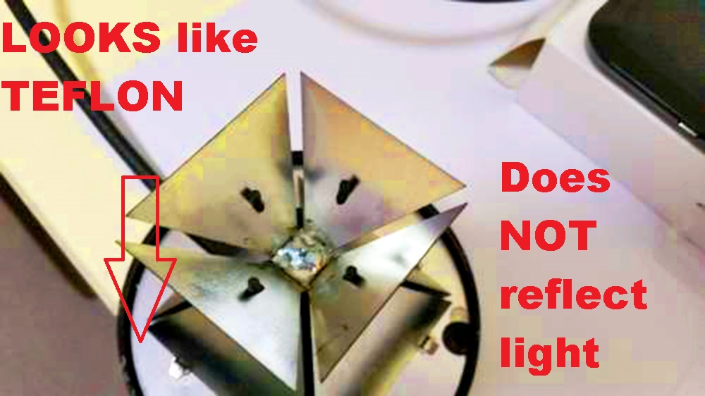
BI CONE , central feed wide band (base is dielectric)
-
BI CONE , central feed wide band (base is dielectric)
-
-
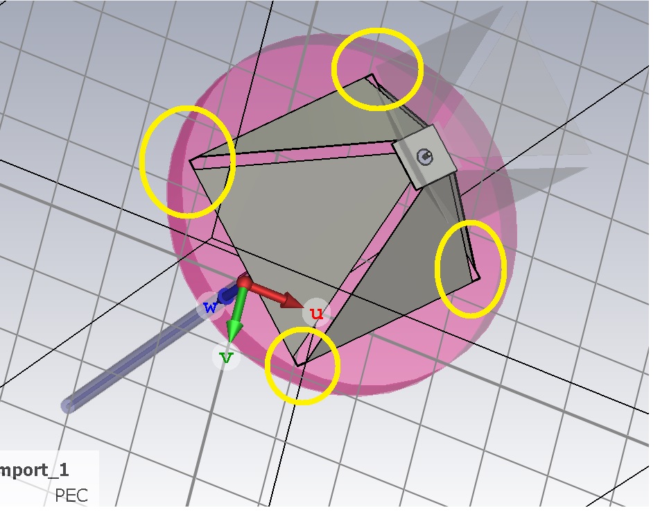
THIS I SEE might be YOUR main problem...(Cut again to eliminate the bridging between CONES , it should be open and the disc is plastic)
-
-
Jomy do you have an stl file i'm interested on check it...?
-
6 hours ago, papagayor said:May the double port cause the lower dbi gain or the whole parts placement
Does it have two connectors...?
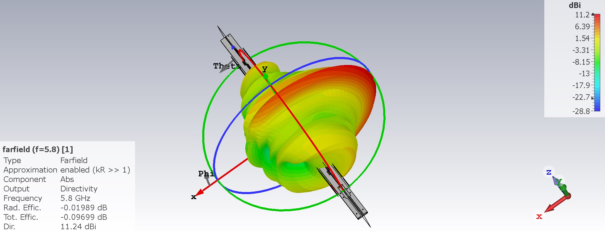
Reactivity is high and Z should stay closer to 50 ohms... to be ideal...
1 person likes this -
Trevor approach seems the Right on the money! BUT it's using an OFFSET DISH...No SHADOW from feed and different focus F/D ratio spillage etc,
-
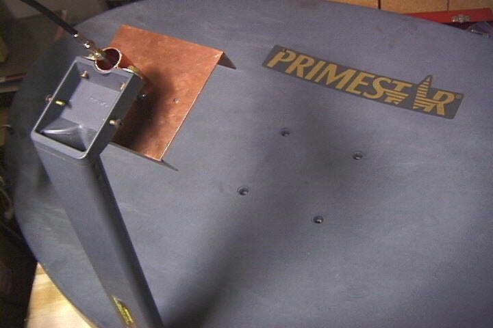
2 hours ago, Admin said:Clanon, the boy has a biquad antenna...!!!
is goin to be a BIG secondary reflector and Biquads have an almost spherical lobe IIRC (better suited for a DISH )
-
Secondary Reflector (small one with similar angle and shape as MAIN reflector) is of MOST IMPORTANCE and antenna should be BACKFIRING (looking back) otherwise you're JUST shielding it from back signals...
-
-
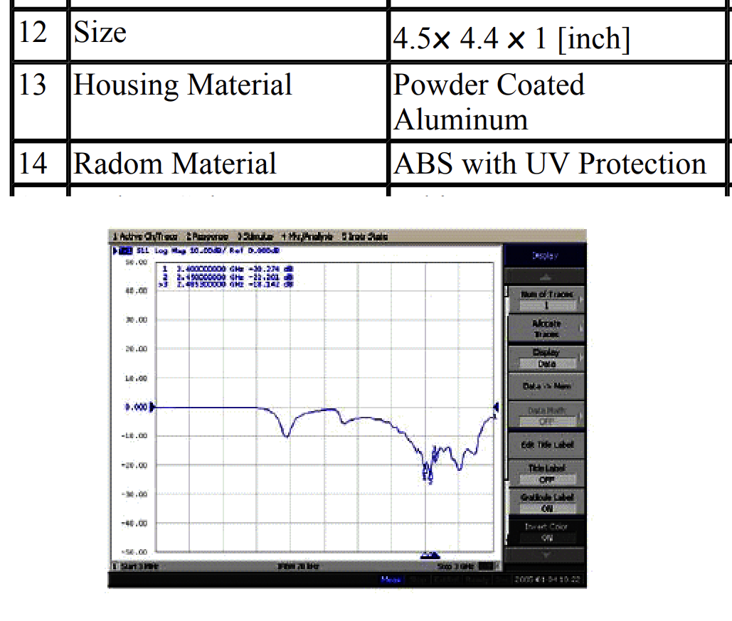
Radome seems THICK 2mm PC (Polycarbonate)
Those big BOLTS must have some effect too...

-
19 hours ago, KSM said:How are the power lines calculated for such an antenna?
Is it the same as for printed circuit boards, where only air is taken into account as a dielectric, or are different formulas used?
Also, why is the element with the director bolted to the reflector at the centre of the element?
Phase and Impedance matching( Radiator Z + Feed point z)
Yes ALL ANTENNAS are the same ; any conductive material) Dielectric must be CONSIDERED (different ε (epsilon), and Tangent Loss)
A HALF WAVE radiator could be held at center point cause there is a Low impedance (high Current) point no EFFECT on general characteristics...(the WAVE is NOT MOVING at THAT specific POINT)
-
we SHOULD make a DATABASE and keep it in the cloud with our CSTs and 3D or DXF files , for the interested in trying them...
1 person likes this -
18 hours ago, nestiam said:My G4AR indicates it is receiving a good 5G signal. I just don't know which leads off the exterior antenna (5G Main or 5G AUX) to connect on ANT 1, ANT 2, ANT 3 or ANT 4?
not sure manual CALL'em ANT1 ANT2 ANT3 ANT4
-
-
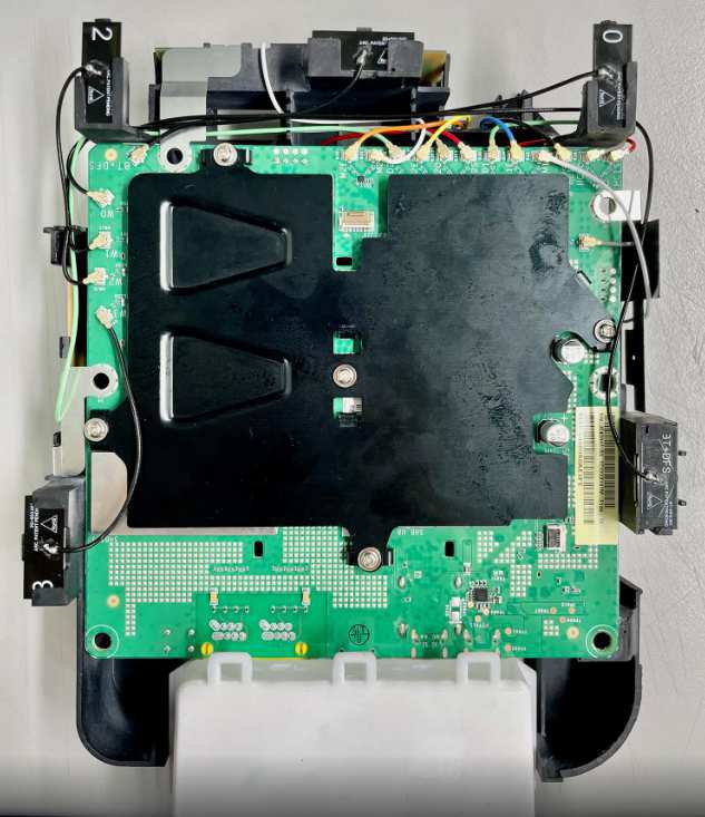
TAMP125 NO IDEA...but nestiam might open the box and SHOW US...
the receiver has a lot of netbook antennas inside (no good)
in Modeling antennas
Posted
You use WHAT WORKS (that'll be DISCRETE PORT 1st and WAVE Port at the end) Same for Solver mesh settings