Register now to gain access to all of our features. Once registered and logged in, you will be able to contribute to this site by submitting your own content or replying to existing content. You'll be able to customize your profile, receive reputation points as a reward for submitting content, while also communicating with other members via your own private inbox, plus much more! This message will be removed once you have signed in.

eddyann
Members-
Content count
7 -
Joined
-
Last visited
Posts posted by eddyann
-
-
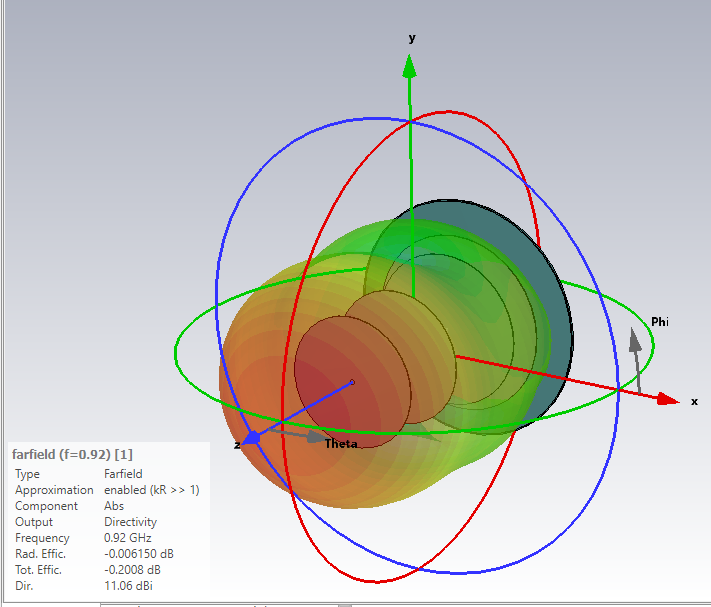
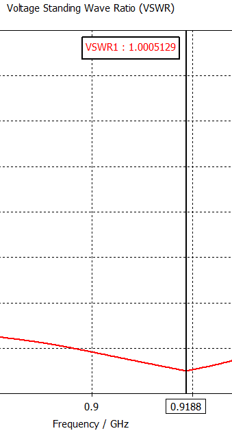
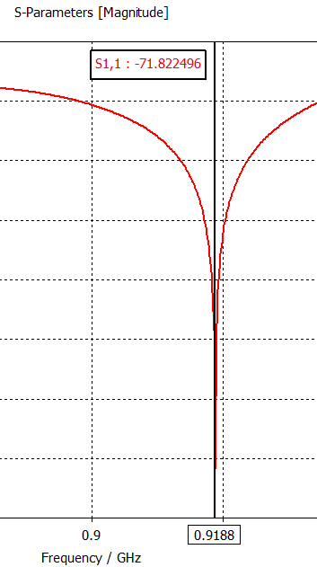
The antenna working frequency should be well enough to operate from 898 MHz to 934 MHz which suitable for UHF RFID application. I will share later once the antenna has been constructed and tested with the network analyzer
 1 person likes this
 -
On 5/15/2023 at 11:36 AM, Admin said: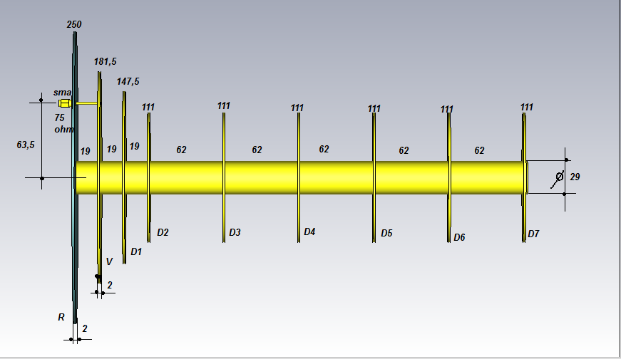
you dont use cantennator for this dimension? I want to get the dimension for 920 MHz with 50 ohm
-
1 hour ago, Admin said:,,,you work with CST...???
I'm currently learning to draw and simulate disc antenna using CST software. Still new and learning. I still cannot find the formula to get the feed point / inset feed location. Some said it is about ~1/3 from the V or the radiator
-
44 minutes ago, Admin said:,,,the feedpoint is chosen relative to the vibrator and not to the reflector...!!!
,,,as you can see, this is chosen to ensure a wide frequency band...!!!
oh ok, so the feedpoint location is it safe to say around ~ 1/3 length location from the center of the V? I still cannot find the correct formula for this. or is it to be autocalculated in the CST software?
-
On 1/30/2023 at 11:29 PM, Admin said:,,,other dimensions, another wifi-shotgun antenna...
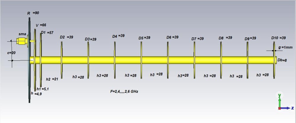
feedpoint (SMA) to the center c=20. is there any standard method on the calculation? most of the time it is about 1/3 to 1/4 from the R=90 in this case
in HF, VHF and UHF
Posted
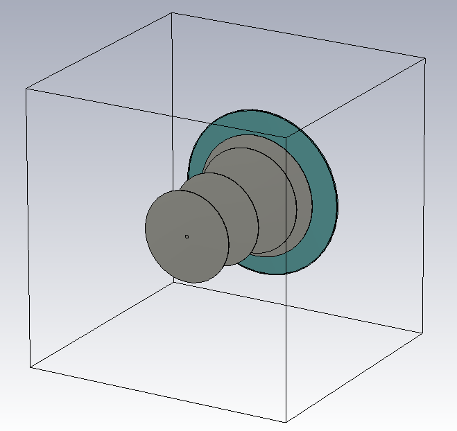
The dimensions (in mm)
Diameter =
dr reflector 240,
dv driven 179,
d1 director 1 154,
d2 director 2 135,
d3 director 3 133,
disc thickness 1
boom 5,
feedpoint from center 65,
boom length 210,
Gap =
dr to dv 15.5
dv to d1 21
d1 to d2 88
d2 to d3 78