Register now to gain access to all of our features. Once registered and logged in, you will be able to contribute to this site by submitting your own content or replying to existing content. You'll be able to customize your profile, receive reputation points as a reward for submitting content, while also communicating with other members via your own private inbox, plus much more! This message will be removed once you have signed in.

Mishka
Members-
Content count
35 -
Joined
-
Last visited
Posts posted by Mishka
-
-
It's intersting to put it into a parabolic dish.
-
1 hour ago, Admin said:,,, and here is the situation with this log-per...
I think there is still work to be done on this antenna ... !!!
Wow! Nice!
Please note, in the NEC model it's fed by a balanced source, and for my assembly I've rotated the SMA connector by 90 degrees (unbalanced feeding).
Well, as for ultra-wide band (2.4 - 7GHz) it looks not too bad. It seems all LPDAs are sort of compromise between bandwidth and quality. At least the model and implementation proves the gain is at about 7dB. Assuming a nice and big reflector which may add up to 20dB, should we consider the Kroks KNA+27 antenna in the subject may virtually go up to +27dBi?
-
1 hour ago, Admin said:,,,thanks,I"ll make a cst-simulation...!!!
Thank you! That would be very cool indeed! I still haven't found a Windows computer for that :-(
-
2 hours ago, Admin said:,,,interesting...!!!
,,, can you give the dimensions ... ??
Sure!
 1 person likes this
 -
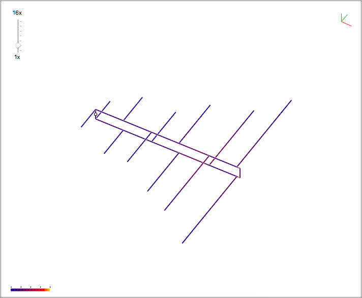
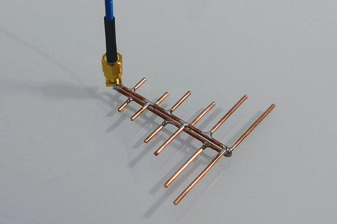
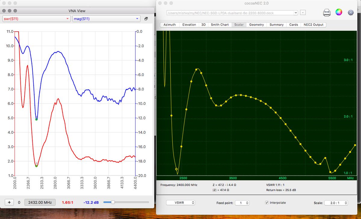
For curiosity I've built the cocoaNEC generated dual-band LPDA. Well, the good news is that the VSWR and return loss are close to what was predicted by the NEC. Please note, the antenna was calculated for 2.4GHz and 5GHz WiFi ranges only and should not be expected to work outside of the bands. Also, my VNA can't see above 4.4GHz so unortunately I was unable to test it at 5 to 6 GHz range.
On the other side, antenna is out of impedance (which is sort of okay for LPDA). This may happen due to improper connection or other assembly issues. Such, for simpler assembly I've soldered a PCB edge SMA connector to the boom - this way the connector will fix the boom distance, but it appears to introduce phase shift between ground and the feed point. Also, the antenna assumes balanced input and this may also put it out of impedance. I'm thinking about adding the impedance matching stub like it was done by Andrew McNeil in the video above. Any thoughts on how to bring it to 50Ω will be highly appreciated.
Measurements:
Spoiler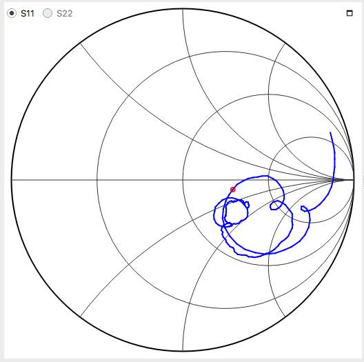 1 person likes this
 -
3 hours ago, Admin said:,,,to see this...
Very interesting video. The impedance stub is a nice finish.
But I had difficulties to read cursor values on the network analyzer screen. It seem about to measure antenna return loss, but it's around 50dBm and changes insignificantly - the chart is 0.5dB/.
-
On 11/21/2020 at 10:17 AM, Admin said:,,, watching this video, I considered it necessary to try to design a Bester antenna made of FR4 fiberglass....
,,, so I present below the simulation designed and sketches for making the antenna....
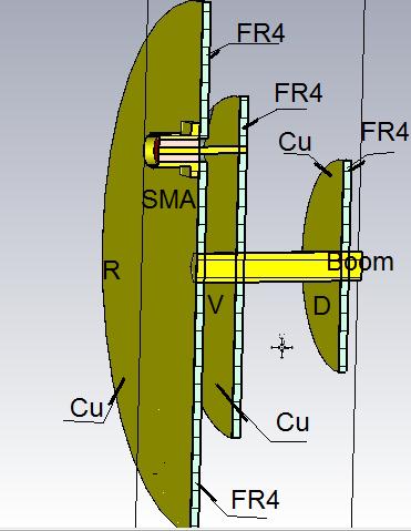
How do you think, would make it two sided with via stitching improve it in any way?
-
11 hours ago, Admin said:OOPS,,, this antenna does not work...
Please hold on, an LPDA works by shifting phase across the boom. Every dipole must be fed with phase rotated 180º so it should look like this:
 1 person likes this
 -
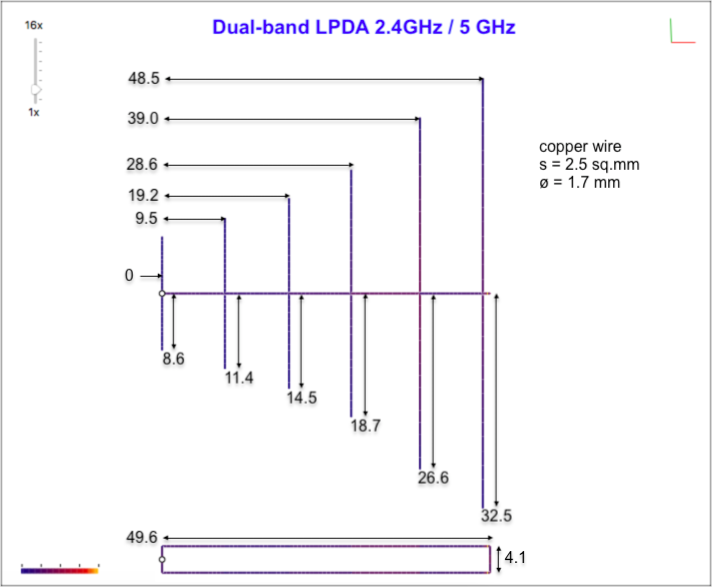
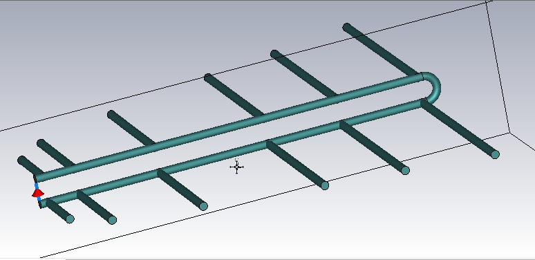
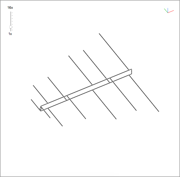
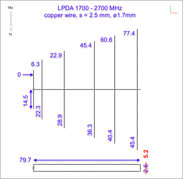
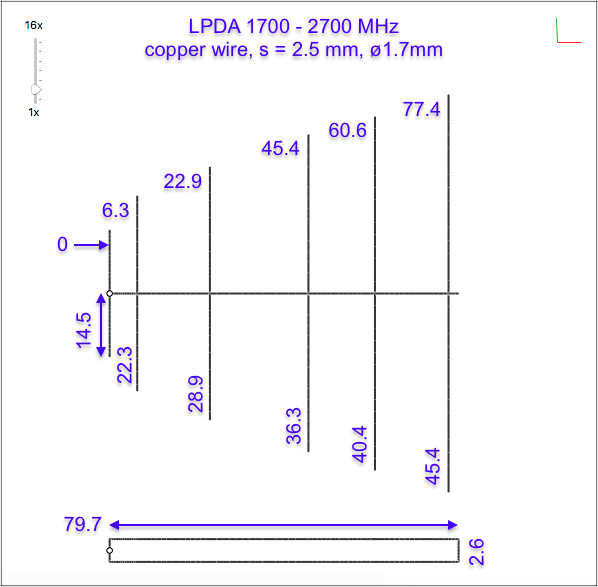
3 hours ago, Mishka said:Here we go. LPDA 1700-2700 MHz, it's made of 2.5 sq.mm copper wire and has 6 dipoles in total.
OOPS!
On the antenna drawing the distance between wires in the boom is 2.6 * 2 = 5.2 mm!
The NEC model is symmetrical, so 2.6 is the distance from the axis (zero) to each wire.
-
7 hours ago, Admin said:,,, dimensions, please ... !!!
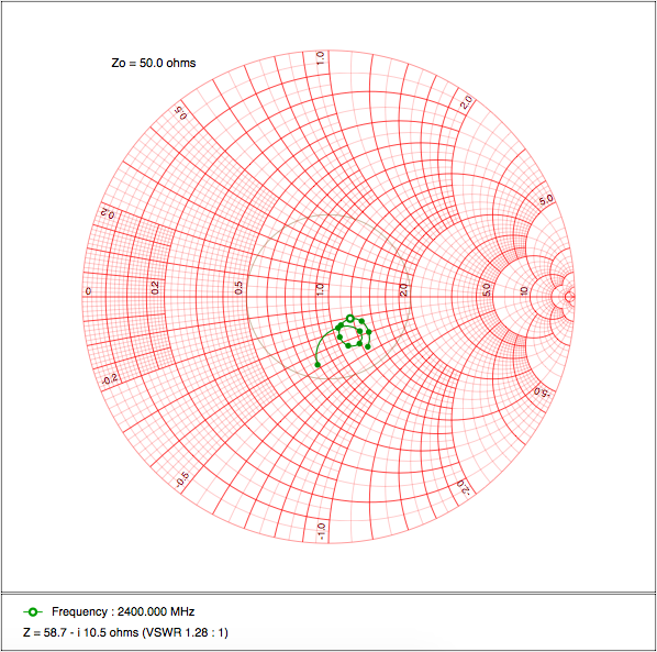
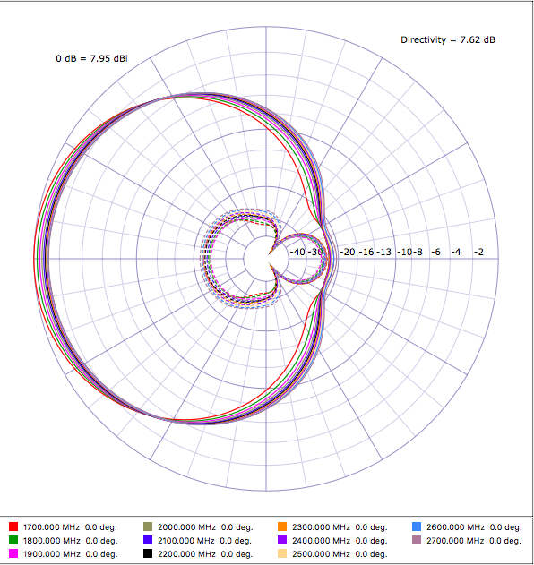
,,, or, I may need to install the NEC program again...!!!Here we go. LPDA 1700-2700 MHz, it's made of 2.5 sq.mm copper wire and has 6 dipoles in total. All dimension in mm. Antenna is [loosely] matched to 50 Ohm, but looking at the Smith chart it seem behaves closer to a dipole. Antenna fed with a symmetrical source.
Of course, a tin-plated version will have different dimensions. As I mentioned earlier, to simulate it there's must be function for a wire mesh. Not too complicated to write though, but I'll be happy if you guys could do it in the CST.
Simulation data:
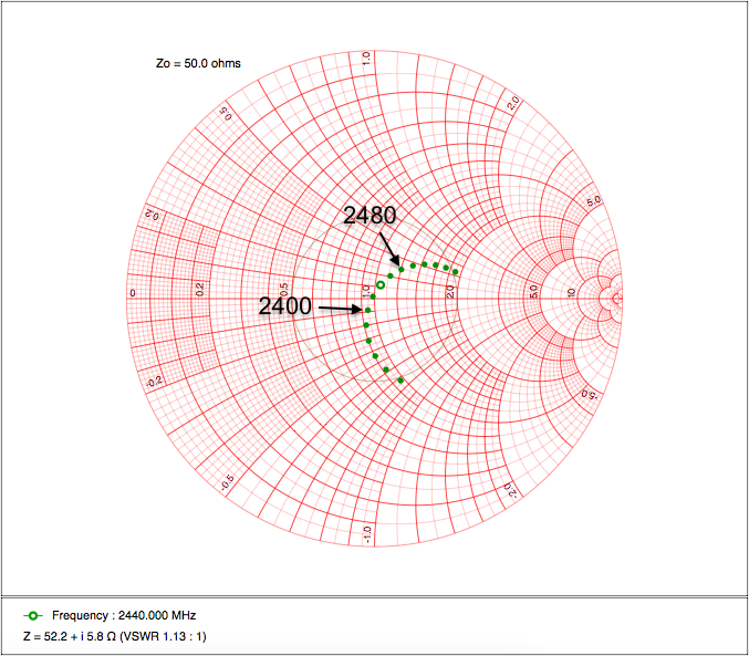
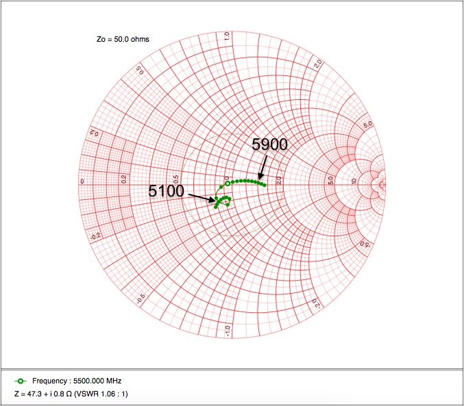
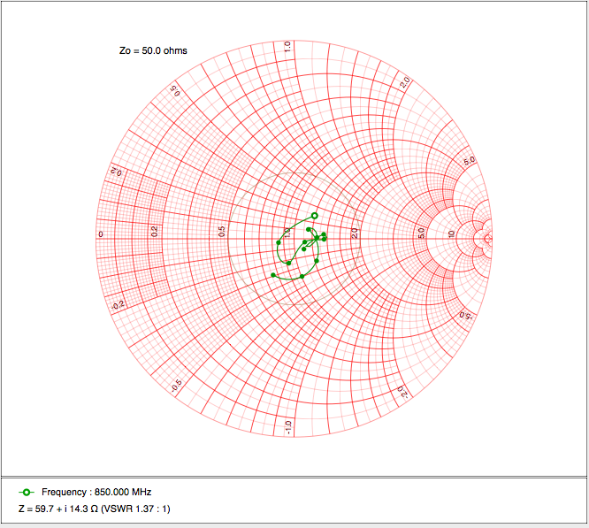
SpoilerSmith chart:
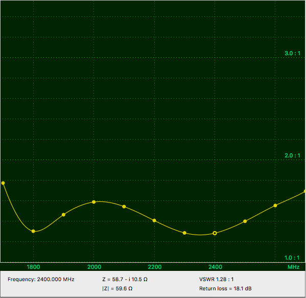
VSWR:
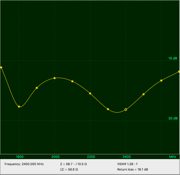
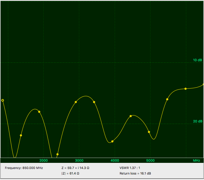
Return loss:
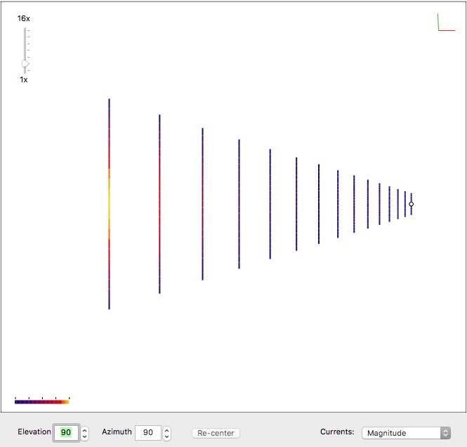
Azimuth (horizontal - solid, vertical - dashed):
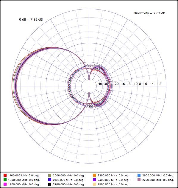
Elevation (horizonal - solid, vertical - dashed):
 1 person likes this
 -
1 hour ago, Admin said:,,, dimensions, please ... !!!
,,, or, I may need to install the NEC program again...!!!No need to bother, please just wait for a while - the SGD is not fast because it's running on top of interpreted language. I'm calculating now.
-
Hey, the KNA-27 is built of six dipoles, not five as I counted initially!
But there's more! When I entered its parameters - 1700-2700 MHz bandwidth, 5 dipoles - into my NEC script, it resulted in a model where the third dipole is clearly missing. Interesting.
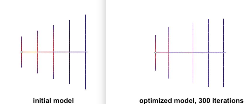
Of course, the model is optimized (Smith chart inside the spoiler):
Spoiler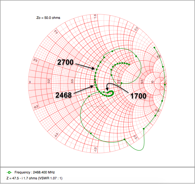
I'll re-run for 6 dipoles now.
-
3 hours ago, Admin said:,,, okay, it's enough to just give the dimensions...!!!
I can easily do it for a wire wound antenna. Is this what you meant?
Or I could model a non-MIMO LPDA similar to the KNA-27. The optimized model will give starting values for dimensions to play with.
-
1 hour ago, clanon said:CST is GUI intuitive...fast and efficient...
(no need for code or commands)
Although the NEC itself is pretty old piece of software, the cocoaNEC has its C-alike programming language so it's possible to calculate parameter values using a custom optimization algorithm. This is especially useful when there is no strong antenna theory behind the model and there are a lot of parameters to tweak so a simple sweep won't work well. As another example, someone could mention fractal antennas where the antenna itself can be generated.
Therefore I'm expecting the CST (or any other modern toolkit) can automatically perform many parameters adjustment in order to minimize VSWR, return loss, etc. Can it?
P.S. I'm on a Mac, and it seems any modern antenna software requires Windows nowadays. I'll be happy to know if the CST can run gradient descent or something similar over a set of parameters, or if it has a scripting interface.
-
On 11/16/2020 at 9:46 AM, Admin said:Mishka,try to design a log-periodic antenna as above (Kroks KNA+ 800-2700 MHz)
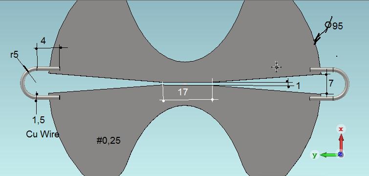
I believe the antenna is made of a single plate, and then bent near the center. Perhaps, the feed points located at a horizontal and a vertical boom sides.
Well, I must admit it's not an easy task to model it in the cocoaNEC. The NEC has support for patches, but the surface of every element must be described in 3D with hundreds, if not thousands of those. I could describe the model with a wired mesh. The mesh will have at least two times elements less and is simper to program. For this particular antenna with five dipoles per side, there are about 20 parameters to optimize - five dipole length & width, plus element to element boom length & width. And there's also the reflector.
Does CST, or HFSS, or FEKO, or anything else besides the cocoaNEC support a programming language, or maybe have a built-in gradient descent or something like that to do the job?
-
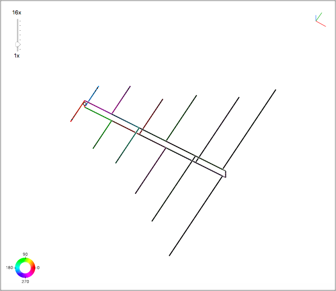
To design something more or less practical, I've put a model for dual-band LPDA for 2.4GHz and 5GHz WiFi into the cocoaNEC. The antenna was designed to be buildable from a copper wire S = 2.5 sq.mm, d = 1.7 mm. All other dimensions including distance between feeding rods (the boom) were optimized for VSWR using stochastic gradient descent. The antenna is matched to 50 Ohms symmetrical input.
Both the NEC cards deck and the cocoaNEC SGD code are available. Please note though, to build this particular antenna I've added 2.6-4.9 GHz band-stop "virtual filter" to prevent SGD from optimizing for the non-interested bands. As a bottom line, it was calculated for 2.2-2.6GHz and 4.9-6 GHz. Considering the WiFi bands only, max VSWR is below 1.4 at 5875 MHz and 2485 MHz.
Simulation data:
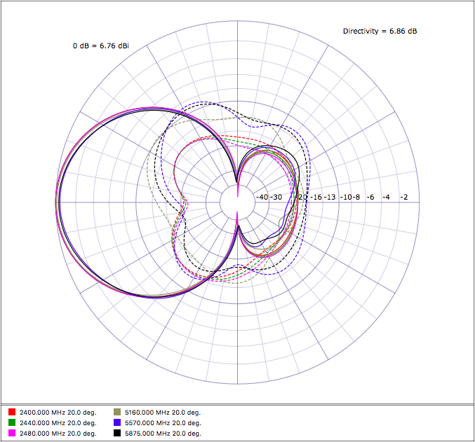
SpoilerAzimuth (horizontal + vertical polarization):
Elevation (horizontal + vertical polarization):
1 person likes this -
18 hours ago, clanon said:What dielectric...?
thickness , dielectric constant...
(there's ALWAYS losses , you know)

The antenna is in free space.
All elements are of constant diameter 0.16 mm or slightly above 6 mils.
-
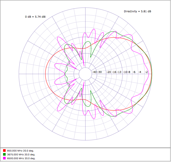
To continue on the LPDAs, there are a number of interesting PCB antennas by Kent Britain WASVJB: https://www.wa5vjb.com/products1.html
I tried to simulate that one at 850-6500 MHz band range with CocoaNEC (no Windows here, sorry) using the method described at https://hamwaves.com/lpda/en/index.html, and eventually reached similar parameters, but my antenna is definitely larger. For 850 MHz the λ/2=17.64 cm, so I'm surprised how WASVJB was able to fit it into the 13.4 cm PCB.
For the simulation I've set tau = 0.85, sigma = 0.12. Element to element transmission line impedance is 75 Ohm. All elements are of constant width 0.16 mm.
Exact location of the elements is as follows (all dimensions in meters):
SpoilerWIRE OFFSET LENGTH 1 0.0000 0.0882 <- quarter wave of 850 MHz, must have two of those 2 0.0423 0.0749 3 0.0783 0.0637 4 0.1089 0.0541 5 0.1349 0.0460 6 0.1570 0.0391 7 0.1757 0.0333 8 0.1917 0.0283 9 0.2053 0.0240 10 0.2168 0.0204 11 0.2266 0.0174 12 0.2349 0.0148 13 0.2420 0.0125 14 0.2480 0.0107 15 0.2532 0.0091Simulation data:
Spoiler1 person likes this -
-
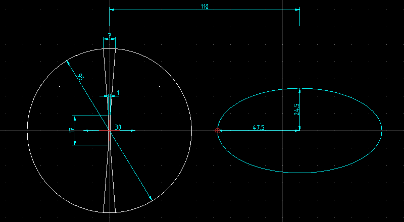
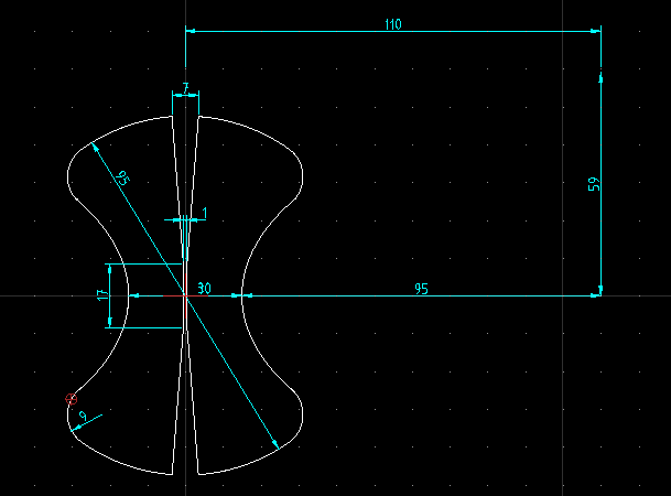
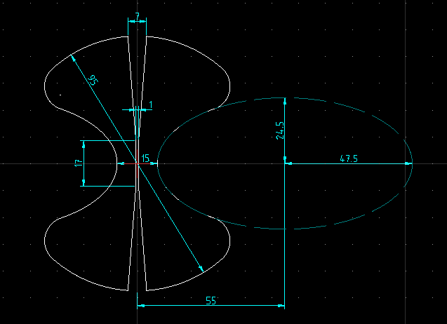
1 hour ago, Admin said:,,, not,,, small radius of the ellipse => 49/2 = 24.5mm and large radius of the ellipse => 95/2 = 47.5mm
the center of the ellipse = 110mm from the 0y axis
I thought my picture above was pretty clear...!!I'm sorry, but this doesn't converge into anything practical :-(
Help needed.
-
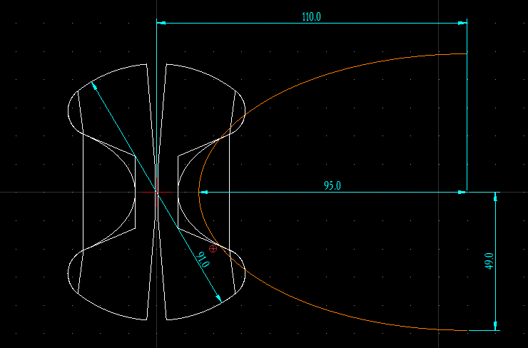
Oops, the ellipse smaller radius is 49 mm, of course. The shape shows it correct, but the drawing dimension is wrong. Please use the updated DXF for reference.
-
On 7/17/2020 at 3:47 PM, Admin said:Okay, here it is. But it looks different from your drawing. Simulation screenshots seem match your drawings too.
What am I missing?
-
Looks very competitive to the Bester antenna.
I think I could put one to the test. But I've found that this drawing differs from content of the DXF files you've published later. So which one is correct?

The DXF as my QCAD sees:
 1 person likes this
 -
3 minutes ago, Admin said:,,, this do you like ,,, ?? parabolic offset 800mm
[image removed]
Yes, thank you very much! Really appreciate it!
I see the simulation data is for 2150 MHz. I'd be grateful if you could do it for 2442 MHz. Well, I don't think it will change dramatically because the batwing is wide band.

in Antennas for mobile communications
Posted
Aieee! I used diameter value in the place of radius in my #cocoaNEC code. Stupid me! Realized this when worked on another antenna.
After changing the NEC model to actual wire gauge (S = 2.5 sq.mm, measured D = 1.66 mm, R = 0.83 mm, but NEC code was optimized for R = 1.7 mm) it became exceptionally accurate! At 2400 MHz, both real (see VNA data inside the spoiler) and modeled values differ by just 0.01 for VSWR and 0.3dB for return loss! This also explains impedance mismatch.
Going to rebuild the antenna now.