Register now to gain access to all of our features. Once registered and logged in, you will be able to contribute to this site by submitting your own content or replying to existing content. You'll be able to customize your profile, receive reputation points as a reward for submitting content, while also communicating with other members via your own private inbox, plus much more! This message will be removed once you have signed in.

Harry36
Members-
Content count
179 -
Joined
-
Last visited
Posts posted by Harry36
-
-
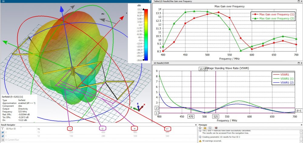
On 10.01.2022 at 3:46 PM, Harry36 said:Narrower range, more gain.
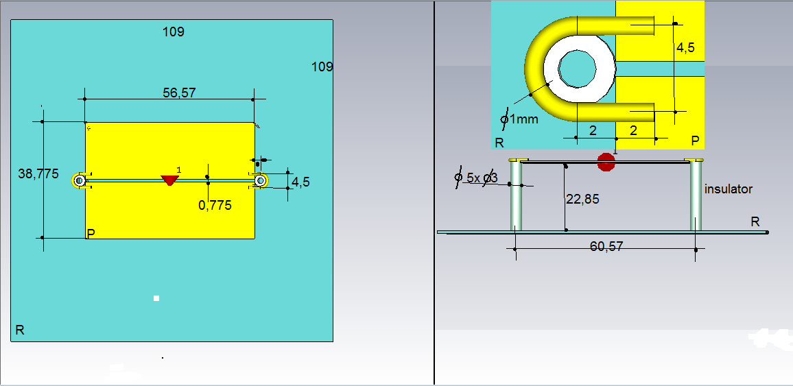
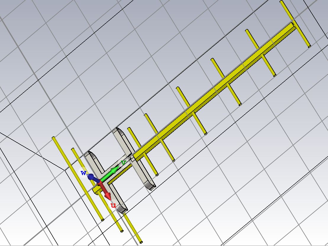
There is a curve in the project.
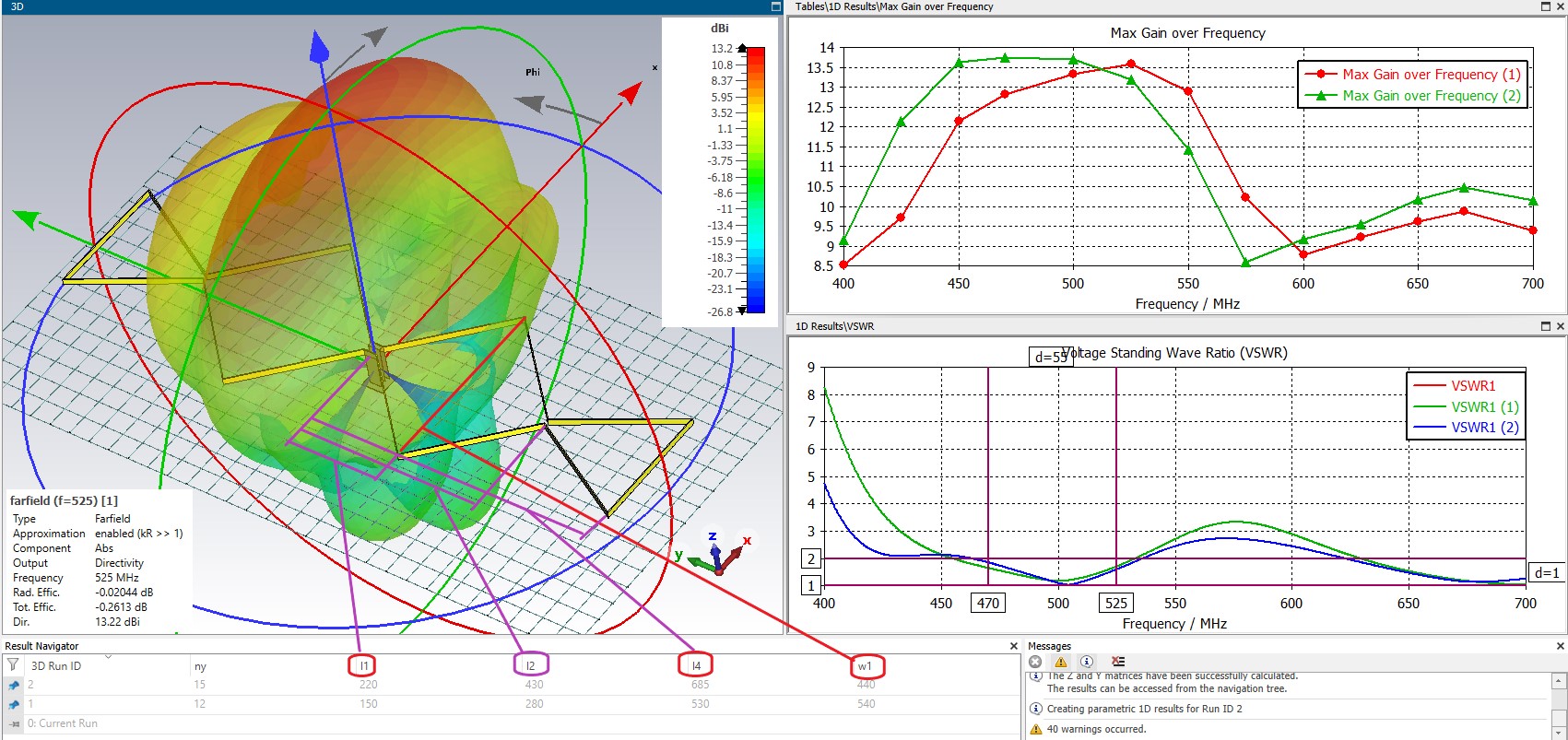
You can change the coordinates with the variables w, w1, w2, l1 ... l4. You can get any shape of the antenna web consisting of straight segments
In Fig. 3, all sides are equal to L / 2 triangle too
 1 person likes this
 -
31 minutes ago, Admin said:,,, but variant 3 does not work .. ???
Narrower range, more gain.
There is a curve in the project.
You can change the coordinates with the variables w, w1, w2, l1 ... l4. You can get any shape of the antenna web consisting of straight segments
In Fig. 3, all sides are equal to L / 2 triangle too
-
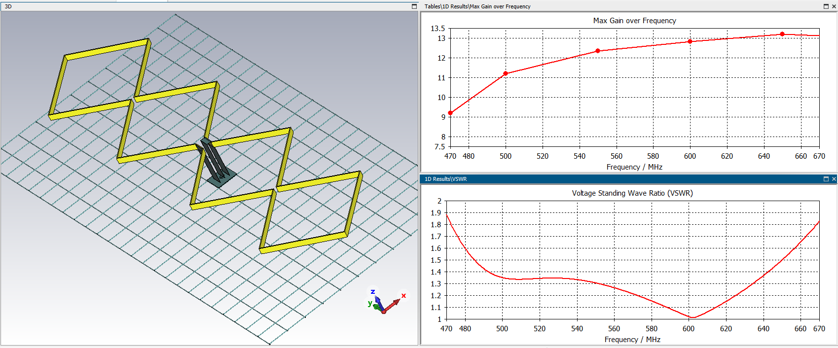
On 08.01.2022 at 7:59 PM, RomanWorkshop said:Will my design TV-dbq.cst (I have only 275x685 mm reflector) work good as TV DVB-T receiving antenna in 470-670 MHz band?
http://patlah.ru/etm/etm-10/tv-anten/tv anteni/a-koefficient/a-koefficient.htm
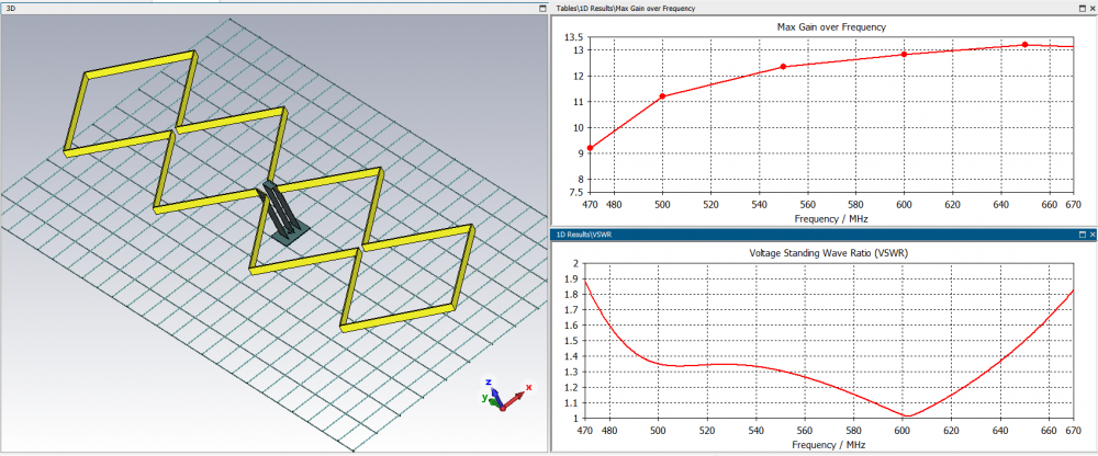
Try this option. Gain 13+ dBi.
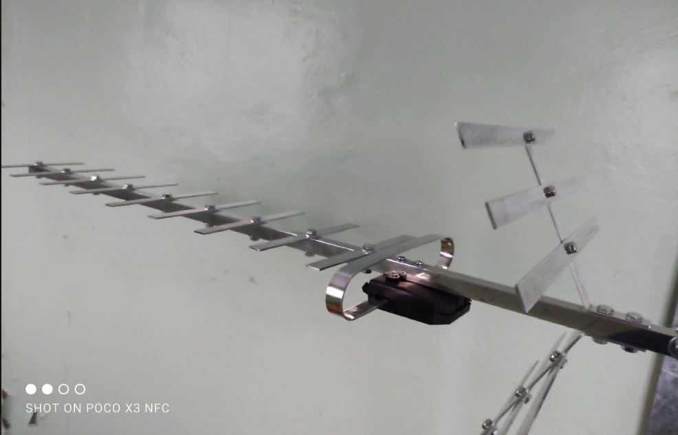
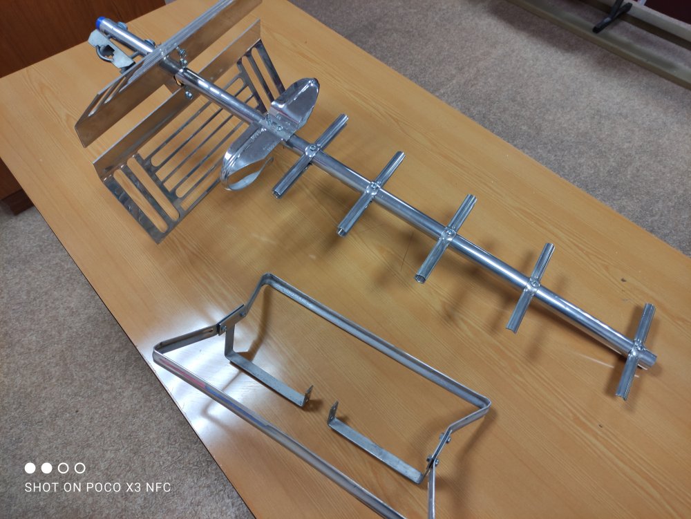
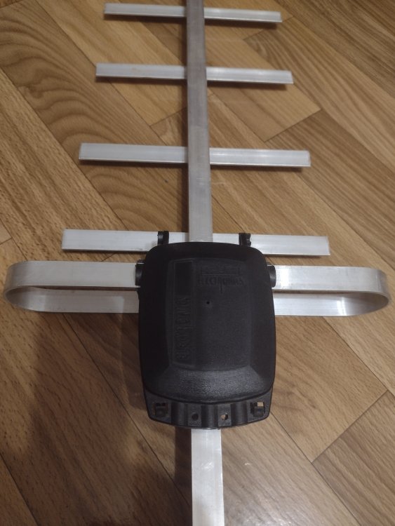
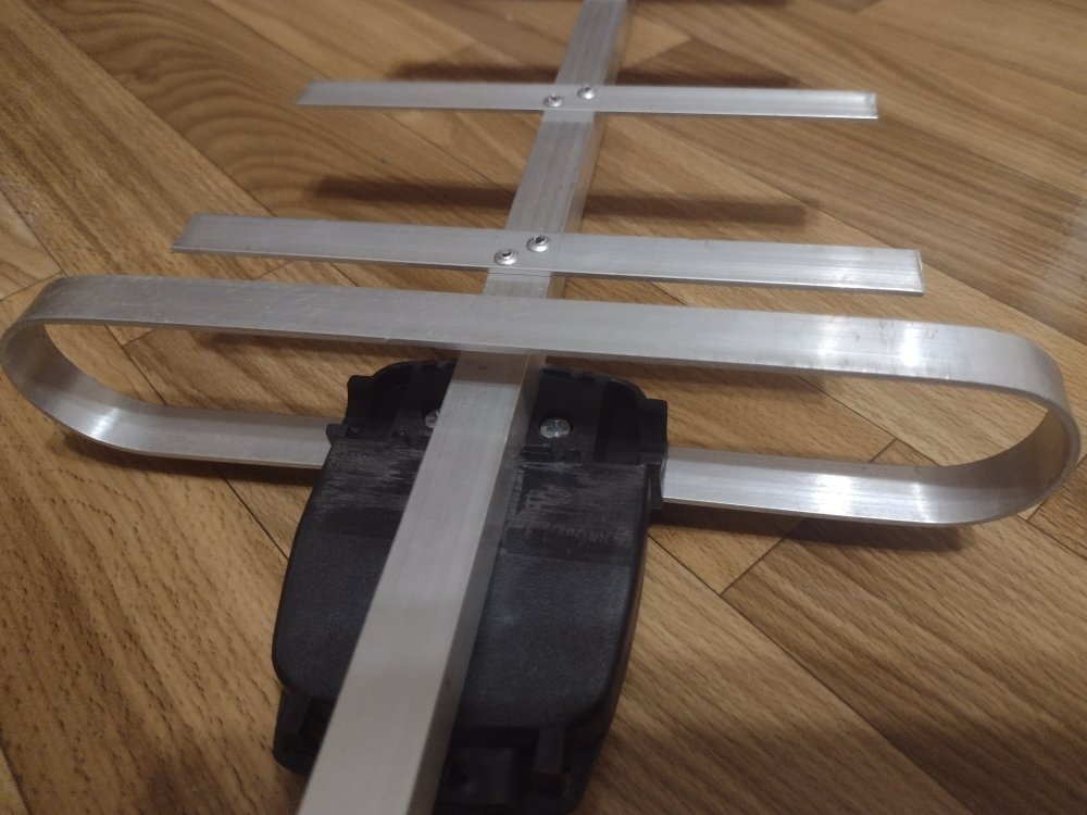
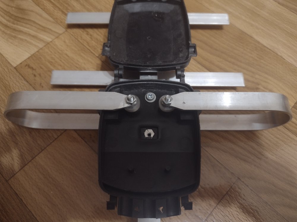
Frame side = 0.375L
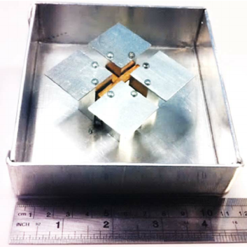
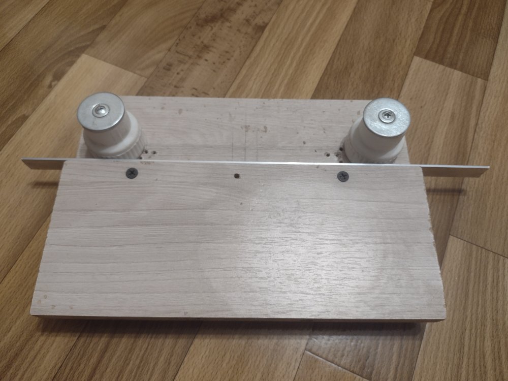
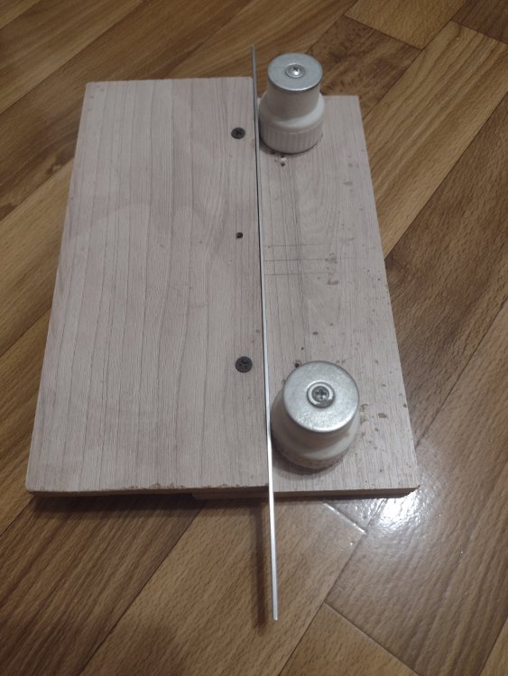
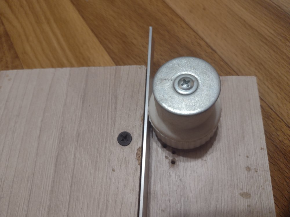
Antenna made of an aluminum strip 15x2 mm and a mesh with a diameter of 2 mm with a cell of 50x50 mm.
Balun stands made of 0.5 mm zinc coated steel.
 2 people like this
 -
14 hours ago, RomanWorkshop said:Will my design TV-dbq.cst (I have only 275x685 mm reflector) work good as TV DVB-T receiving antenna in 470-670 MHz band?
http://patlah.ru/etm/etm-10/tv-anten/tv anteni/a-koefficient/a-koefficient.htm
-
5 hours ago, alhaba.production said:can it coverage lte b8 to b40?
8 hours ago, Admin said:Yes, this type of antenna can cover the 800-1000 and 1700-2400 ranges. But to recalculate the dimensions and add additional elements to the structure.
1 person likes this -
9 minutes ago, clanon said:You need to locate TWO points in map (New Site 1 and New Site 2) + this info

My friend, this is worthy of a separate topic in another section. I can make a lesson using screenshots if someone needs it.
HNY!
1 person likes this -
13 hours ago, Marcello971 said:Thanks for your proposal.
As I said at the beginning I'm a newbie in this field. Based on these results what do you suggest me to do to cover 10km as distance? Which is the best solution?
Sputnik antenna requires also the parabolic dish? I guess the target gain is always at least 20dbi
Then, could you please show me a scheme where I can see how to place the two SMA connectors on the antenna?
Thank you
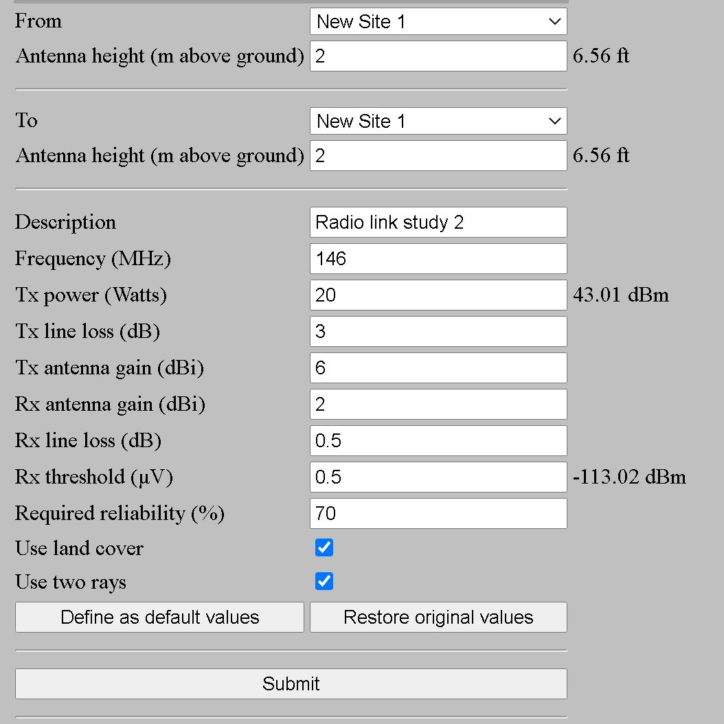
In order to build a connection for 10 km, you need to understand the physics of wave propagation and know a little about geometry. The range is 10 km - over the horizon. Even if we take an ideal “flat” terrain, the horizon for the observer will be at a distance of ~ 5 km. For a line of sight at a distance of 10 km, both points must be raised ~ 8 meters above ground level. If there are obstacles in the path of the link, then the transmitting and receiving antennas must be raised higher. But there are also Fresnel zones that allow you to receive a signal and "without line of sight." Antenna selection should be started by surveying the terrain at the link site and calculating the link budget. By budget we mean not financial resources, but the power of transmitters, antenna gain and losses at a distance. There is a very good service for calculating the link budget. http://www.ve2dbe.com/rmonline.html
try to figure it out and then it will become easier with the choice of antenna.
1 person likes this -
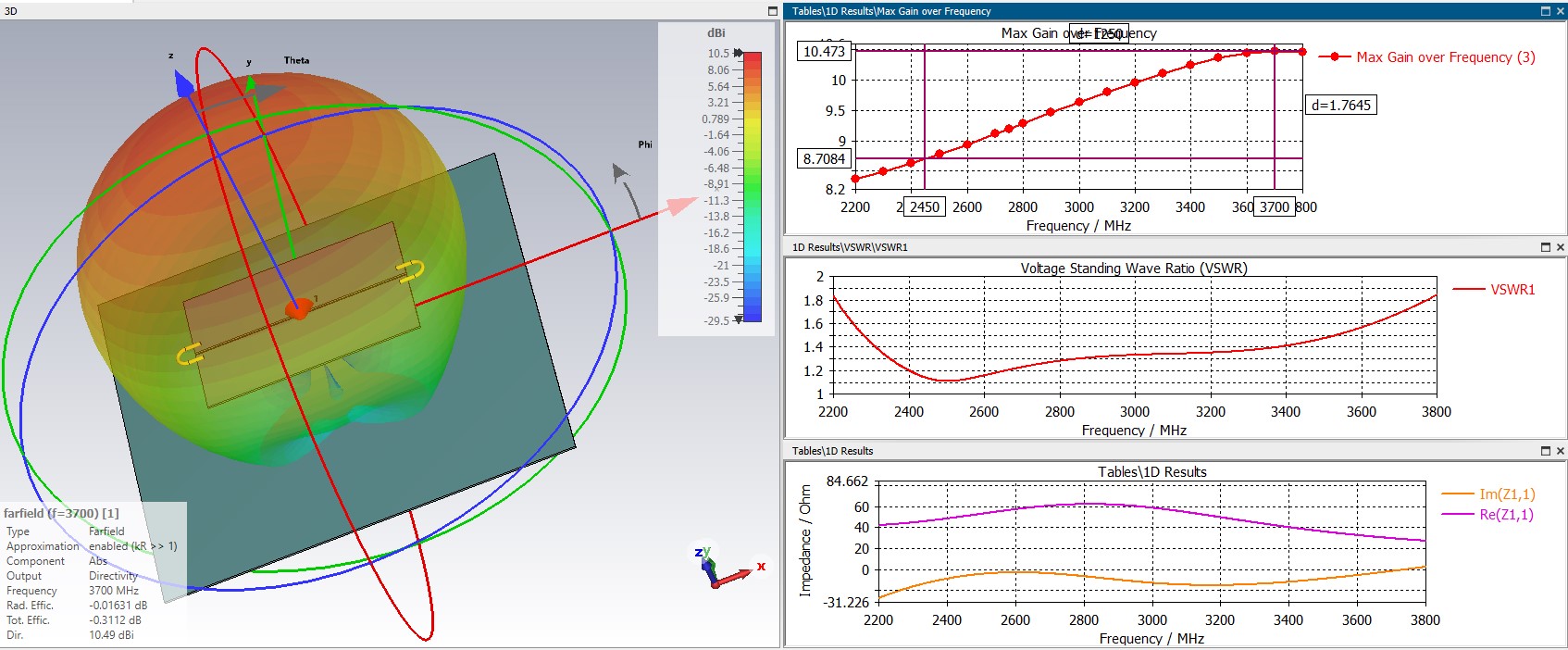
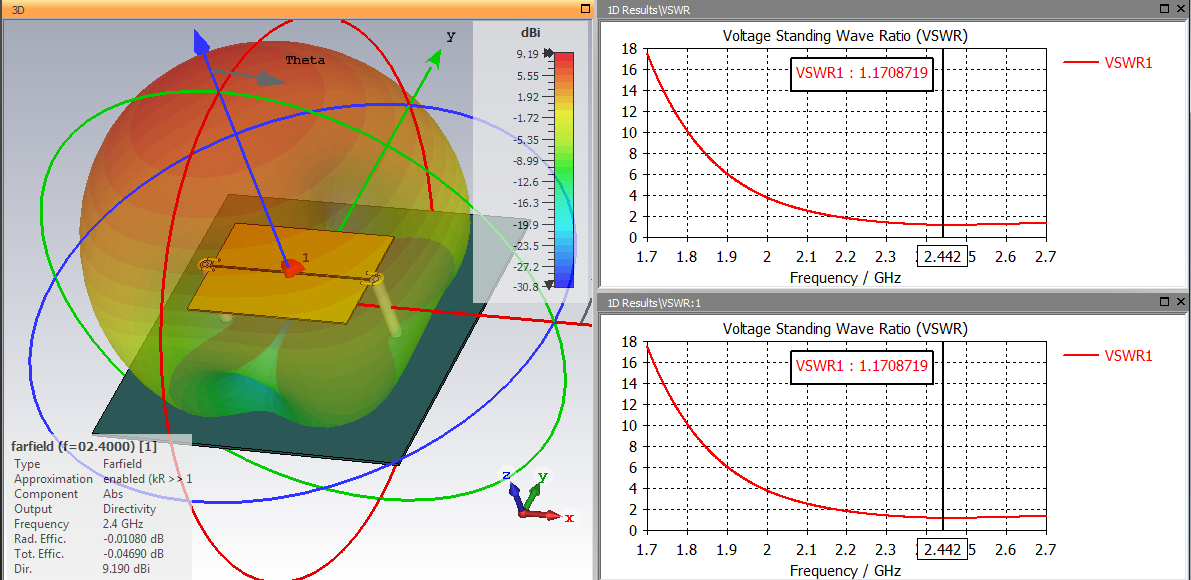
6 hours ago, Admin said:Harry36, with your dimensions, the antenna does not have VSWR <-1,2-1,4 on the frequency band 1,7-2,7MHz....!!!
If you want you can post your cst file....!!!how much will it turn out? 18 how are you? I will not give you the cst files, you are not linking to the original source and posted earlier than I requested. It makes no sense to talk about the final dimensions of the antenna without detailing the power port. Draw a real cable and the characteristics will change.
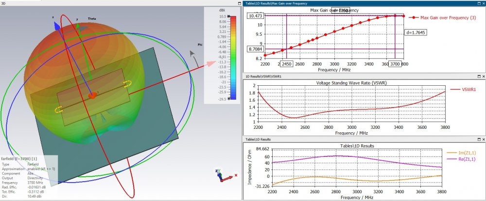
Using your dimensions, you get an antenna for the range 2200-3800 by SWR2. Realizing that at the beginning of the range we have the lowest gain, you knowingly doom the user (2.4 GHz) to a loss of power.(1.75 dB).
For antennas of this type, for use in a narrow frequency range (wi-fi 2.4), it is more advantageous to match at the end of the range in order to obtain maximum gain.
-
On 29.12.2021 at 3:47 PM, Admin said:,,, the simplest UWB antenna, Sputnik antenna...


SputnikV

.thumb.png.0357fa9a1c4bc5e670a78144c8efdb54.png) 2 people like this
2 people like this -
On 23.12.2021 at 4:22 PM, vova.gumerov said:470-800 MHz
 7 hours ago, vova.gumerov said:
470-800 MHz
520-850.
the size needs to be increased for 470-790.
-
On 09.12.2021 at 7:37 PM, clanon said:focus point is important (distance to reflector) some mm make a huge difference...
did you try with antenna (reflector ) at 90 degrees...VERTICAL...?
Edited Thursday at 07:38 PM by clanon
On screen LTE. -/+45°.
Try it.
 1 person likes this
 -
18 hours ago, clanon said:i catched Mikrotik stealing BUT developing over the theft here
yes, this is not the only fact with Mikrotik
Spoiler
 1 person likes this
 -
34 minutes ago, clanon said:easier to STEAL than develop-invent...
nice bandwidth... could it be SHIFTED to 1 ghz (LTE)...? Who needs 3,5ghz...
The 3.3-4.2 GHz band is used for 5G technologies.
n77 TDD 3700 C-Band 3300 - 4200
n78 TDD 3500 C-Band n77 3300 - 3800
n79 TDD 4700 C-Band 4400 - 5000
1 person likes this -
Unfortunately, without the exact dimensions (although I do not see any differences from the original), I do not presume to judge the frequency range, perhaps the reduction of the reflector and the plastic case with the rod played a role. But we all see the fact of theft without the slightest alteration with our own eyes. This is a very sad page in the history of the company.
1 person likes this -
As always, Crox's firm screwed up. The development of 2018 was stolen as an irradiator.
https://ieeexplore.ieee.org/document/8410517
where are the differences from the original?))
1 person likes this -
 3 people like this
 -
I think the reflector is a little small for this irradiator, I would pick up a reflector with a diameter of 120-140 mm in diameter, also reducing the sides to 0.5-1 cm. and in the last photo you can see that the emitter touches the reflector, which should not be
2 people like this -
On 11/26/2021 at 1:01 AM, clanon said: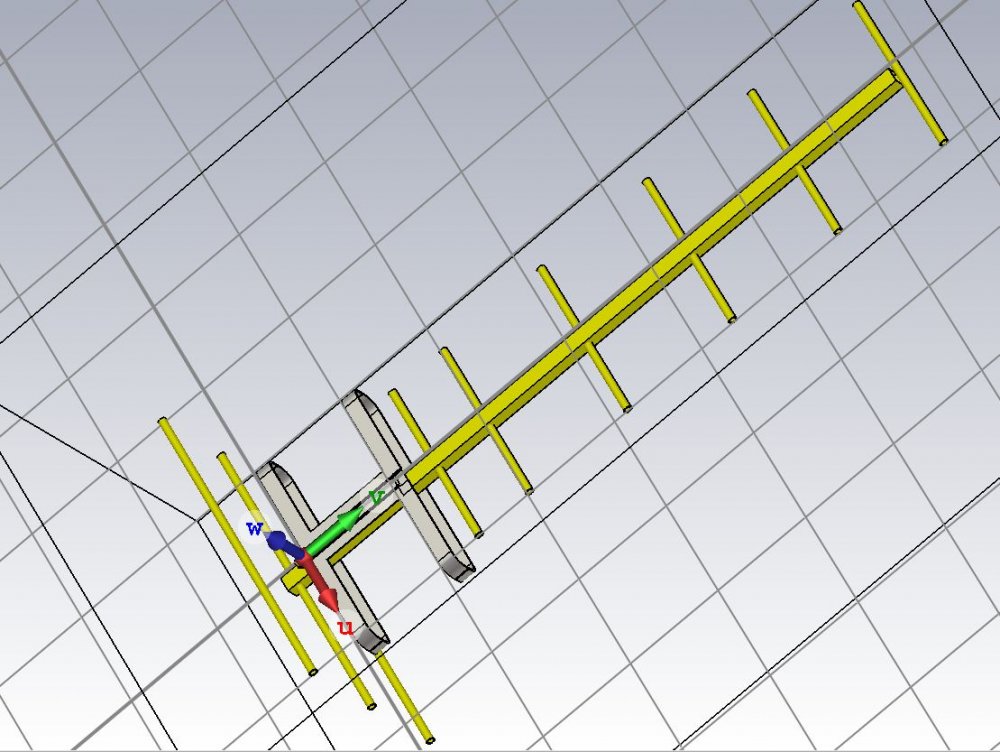
Antex patent ;-)
 1 person likes this
 -
-
1 hour ago, vova.gumerov said:oh it's a long antenna !!!!! I thought that you already calculated the antenna for me and that for 12dbi you need to add + 3 elements ???
Clanon, for one good small antenna, they will give 2 long ones !!!!
On 11/24/2021 at 7:43 PM, vova.gumerov said:better with one!
I thought so!
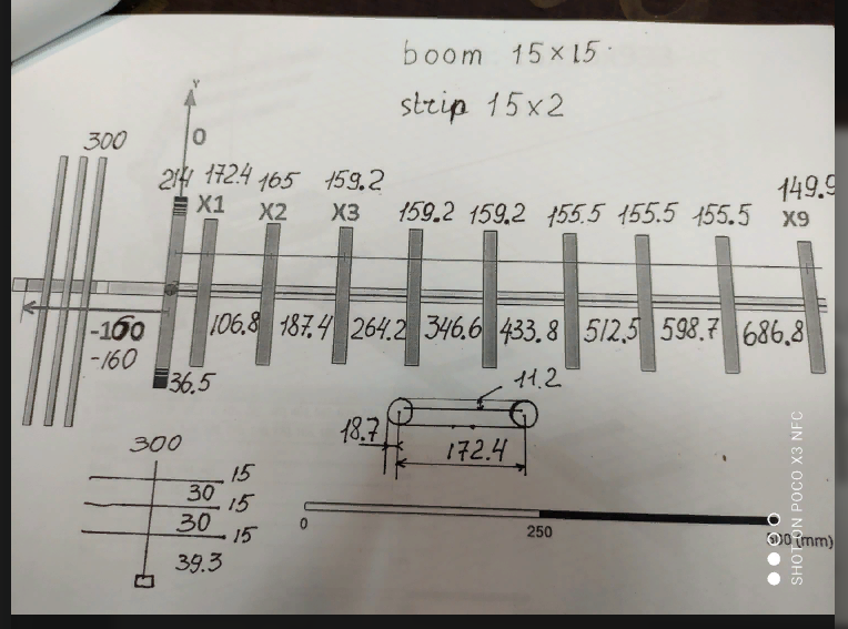
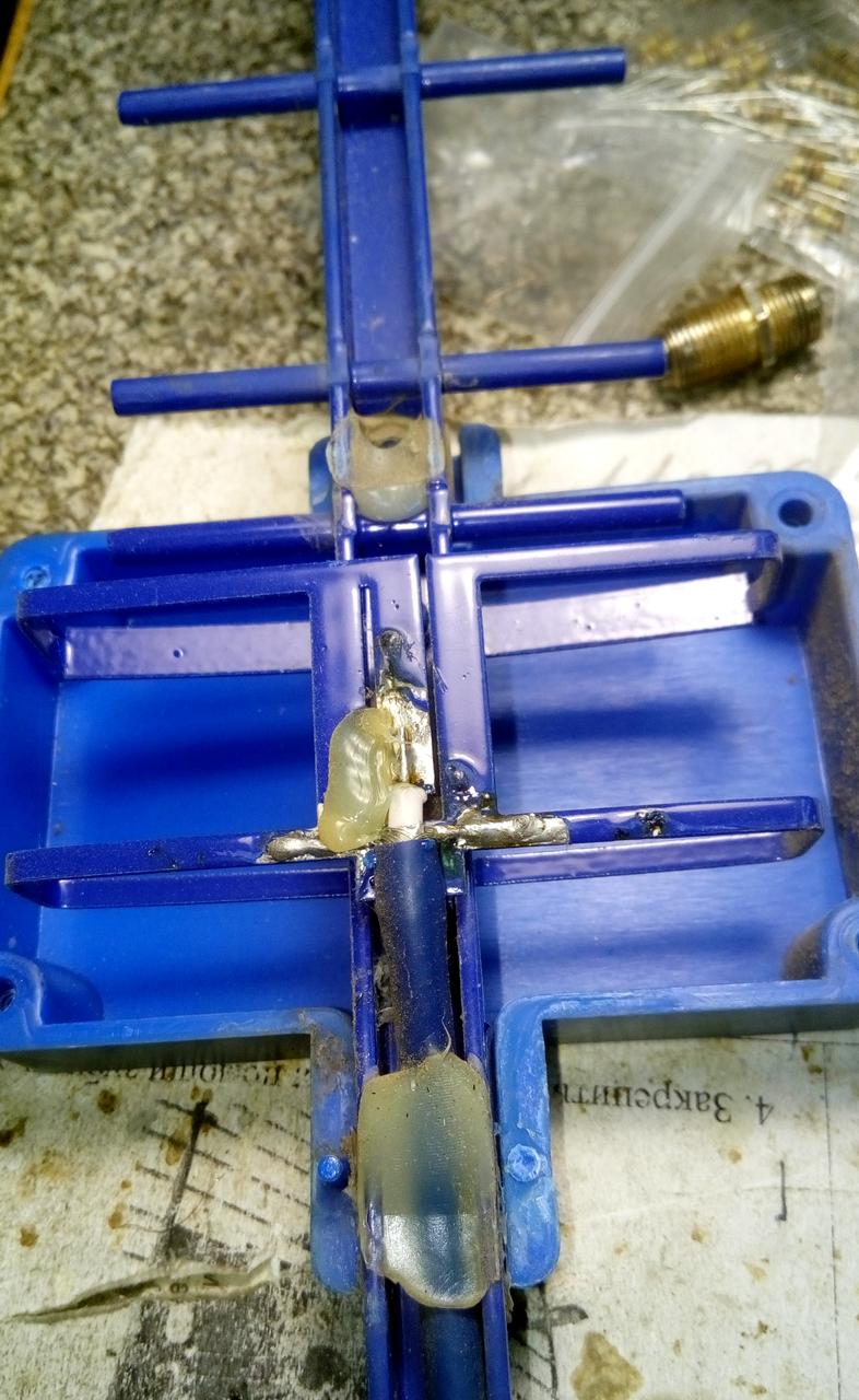
Clanon, they brought me an AL strip today. 15x2mm. This is in addition to the material I wrote to you yesterday!
Vova, this antenna is not broadband. It covers 2 adjacent channels. It is not suitable for your requirements. How long do you want the antenna to be?
http://radiotech.inf.ua/Shematic_PCB/HFtehniks/shpindler_anten.htm
1 person likes this -
19 hours ago, vova.gumerov said:better with one!
I thought so!
Clanon, they brought me an AL strip today. 15x2mm. This is in addition to the material I wrote to you yesterday!
?

 1 person likes this
 -
5 minutes ago, Admin said:,,, do you have the dimensions ... ???
Yes. No dimension balun(((
-
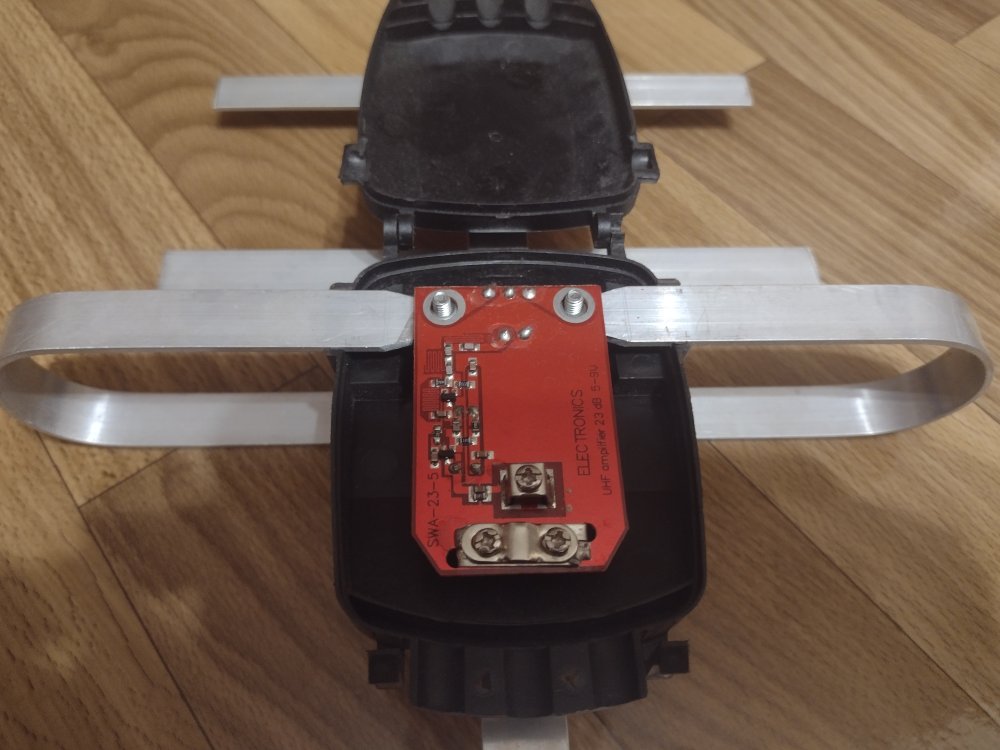
KNA27-1700 / 4200P
-
wswr 3.5. ☹️
1 person likes this
.png.a940f9b213a60e67d9c72858b89b9443.png)


in HF, VHF and UHF
Posted
Balun does not repeat Lira. VSWR and gain are slightly worse than stated. The overall dimensions are slightly larger (due to the size of the mesh cells). Impedance 75 Ohm. Easy to manufacture and not very sensitive to dimensions (+/- 1 mm).
Lira_TV_v3.0.cst