Register now to gain access to all of our features. Once registered and logged in, you will be able to contribute to this site by submitting your own content or replying to existing content. You'll be able to customize your profile, receive reputation points as a reward for submitting content, while also communicating with other members via your own private inbox, plus much more! This message will be removed once you have signed in.

clanon
Members-
Content count
844 -
Joined
-
Last visited
Posts posted by clanon
-
-
-
On 29/11/2023 at 7:15 PM, eco32 said:No one did it with biquad
nope...BUT those complex feed networks steal gain (several db)
-
double post
-
Water absorption should be adressed in PES foam...Changes ALL.
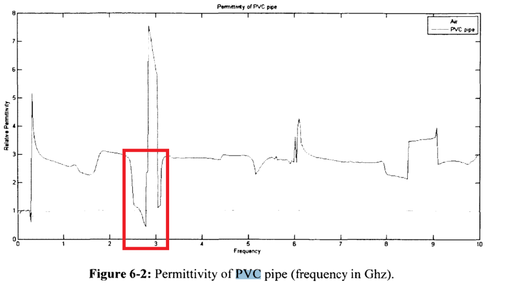
PVC pipe has THIS weirdness...
-
12 hours ago, eco32 said:once again:
Dipole has oposit phase on the arms, biquad has same phase on the both ends, trick with phase shiter will not work here.
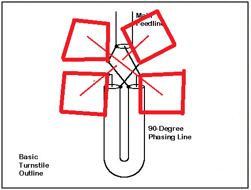
LOOP should be CLOSED at feeding Points...
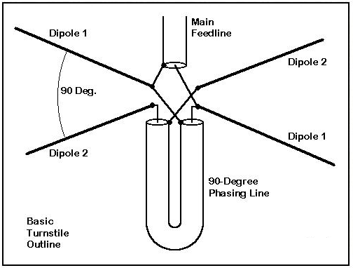
then , EACH Loop should be feed with 90 degrees phase difference
 2 people like this
 -
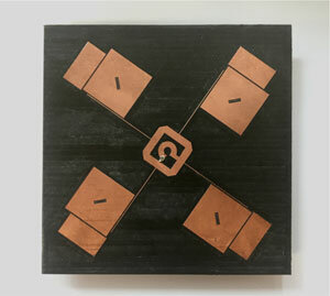
Double lineal here , NOT circular "The polarization of the emitted signal depends on the spatial location of the antenna. Horizontal - horizontal, vertical - vertical polarization. [4] The horizontal position represents when both squares are next to each other, the vertical position is when both squares are placed one above the other."
DoubleBiquadOmni-Antennafor2.4GHzWirelessLinkApplication.pdf
-
On 11/23/2023 at 0:26 PM, eco32 said:Yes, Thank You!!!, it looks like his cross biquad/biloop has 8dBi isted of 10dB from single biquod, without e-field chart it's hard to tell if it's circular polarization in this design there are no phase shifters. In my opinion it has linear polatisation. (I don't have to be right, maybe there is something going on there that I have no idea about)
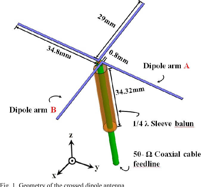
Just only for Example: S-band circularly polarized crossed dipole antenna for automotive applications
YES you treat it like a simple dipole (but polarization is 180 degrees inverted for a double quad)
Then to get Circular Polarization , you need to retard 90 degrees the wave at each quarter making a 0 90 180 270 rotation (for this the easiest approach is a Quarter wave length (dielectric in coax included) from One biquad to the other...
-
On 20/11/2023 at 6:41 PM, eco32 said:Add to previous post:
I know that it is possible with dipoles, because there is an opposition phase on the "arms", I have no idea how to do it with a biquad, it has same phase on opostit cornersit should be possible with a 90 degrees (velocity factor of coax x 1/4 wavelength) between both antennas (but interactions should be simulated)...
1 person likes this -
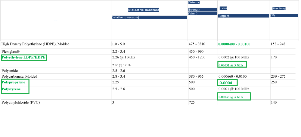
one of the LOWEST in the world 0.0003 at 3000 mhz , only one better Polypropylene...at higher frequencies...5.8 ghz ideal...
-
On 3/11/2023 at 3:40 PM, Admin said:,,,but if galvanized sheet and wire supply lines are used....???
I would give it a go ...BUT with circular patches...we'll see...(you had one like that YEARS ago... mimo...remember...
1 person likes this -
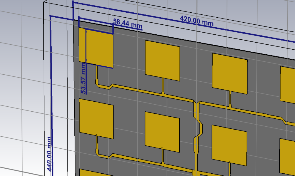
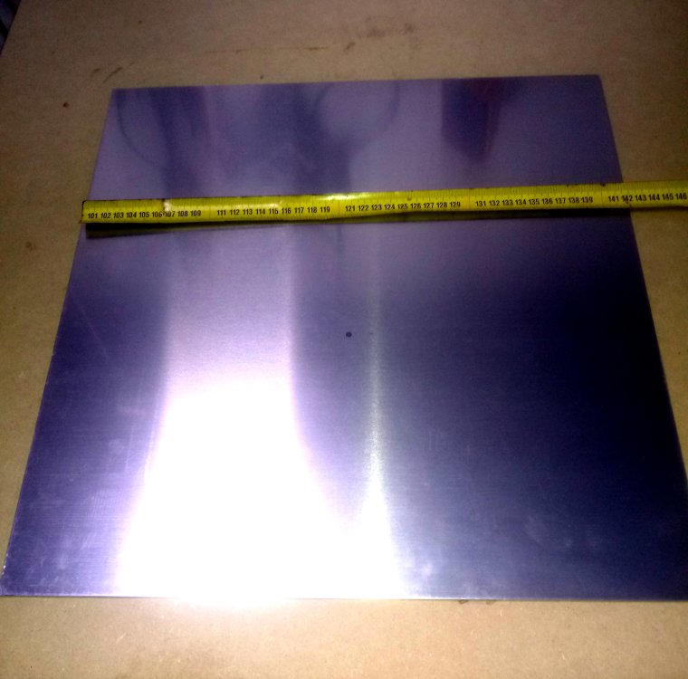
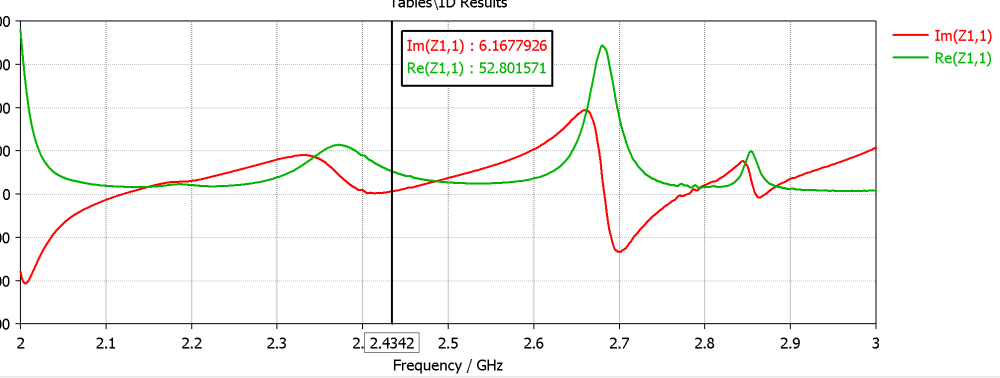
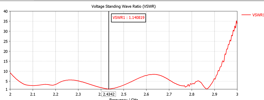
yup...5.84 cm by 5.4 cm...(these are HIGHLY related to the Dielectric Factor , change from 0,4 to 0,5 would change several millimeters these dimensions)
-
it would be interesting...could be Laser cut or stamped...Wires have more REACTIVITY (Imaginary Z) Inductive reactance...impedance curve is always smaller...2mm copper ...maybe...
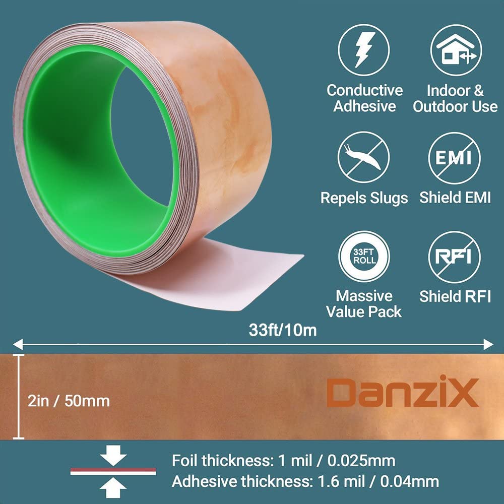
Copper tape is easy to cut with cutter under print drawing taped on top...perfect
you get more losses in the metal distances should stay the same and sizes...
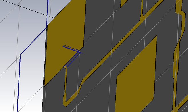
to keep a good Impedance and low 2 mm or LESS from reflector the Feed network
Patches 4 mm or more from reflector (there is a step of 2 mm)
 1 person likes this
 -
-
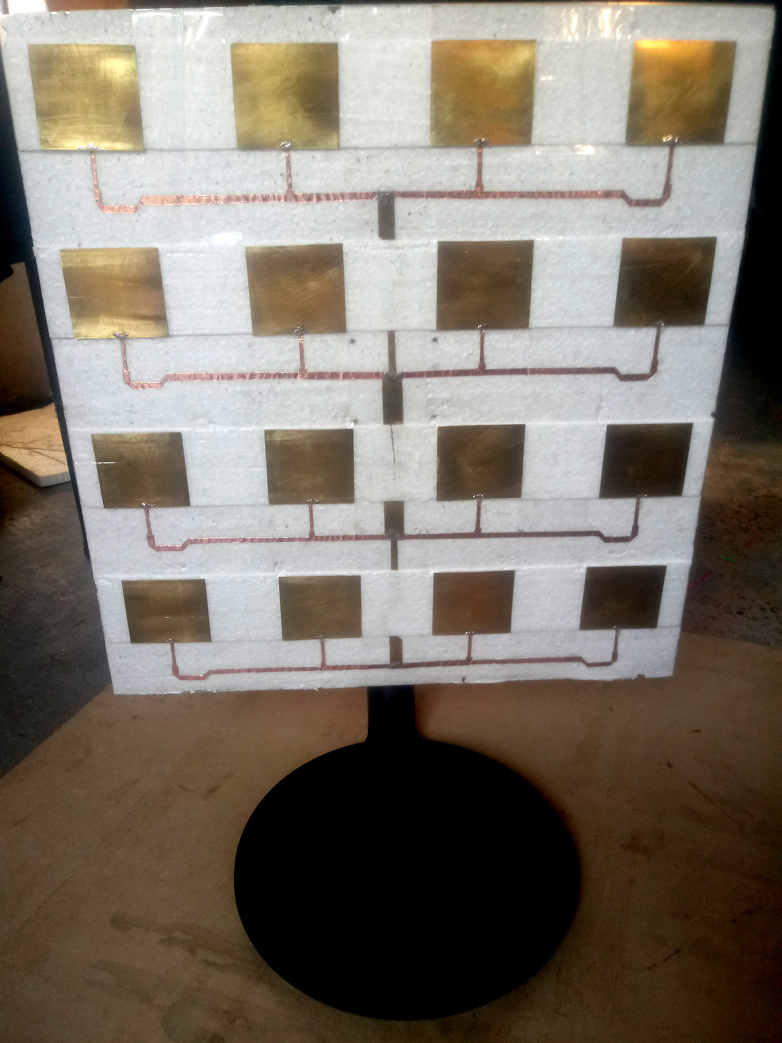
Styrofoam (lowest density better)
cut with resistance wire (nichrome) at 2 mm flat
-
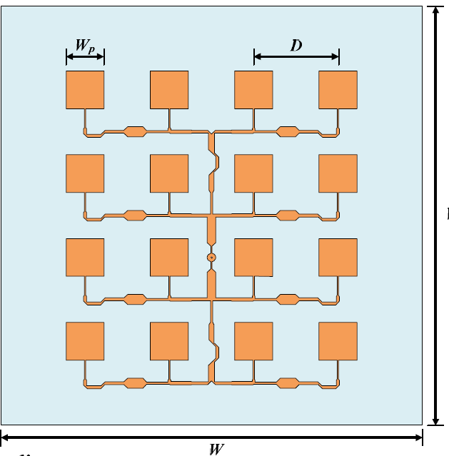
i have A model (my ssd failed with the original but i had the dimensions on paper) could put the dxf of the feed and patches are ALL the same
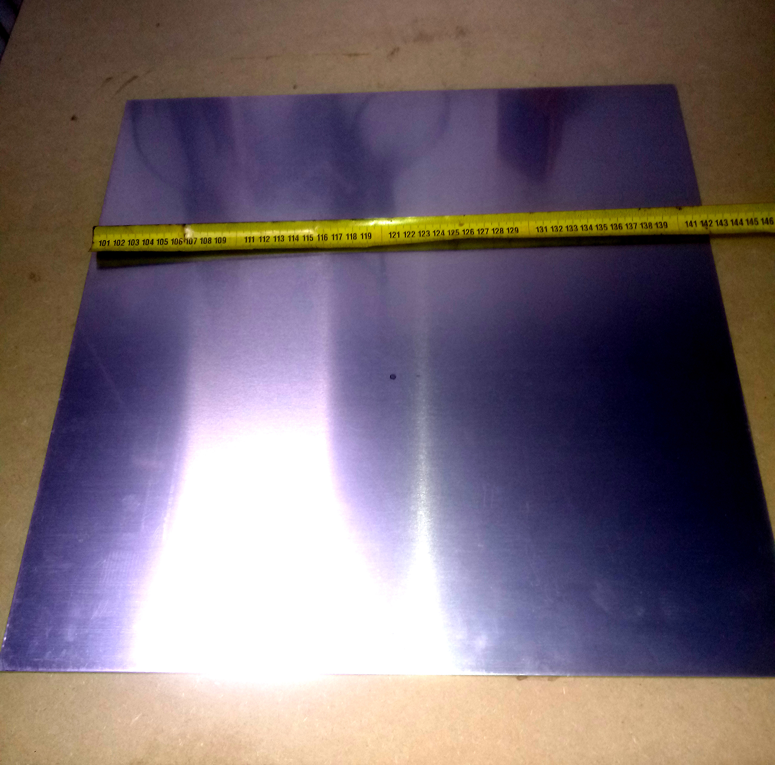
42 by 44 cm reflector
Model should be customized to Dielectric used in each case
-
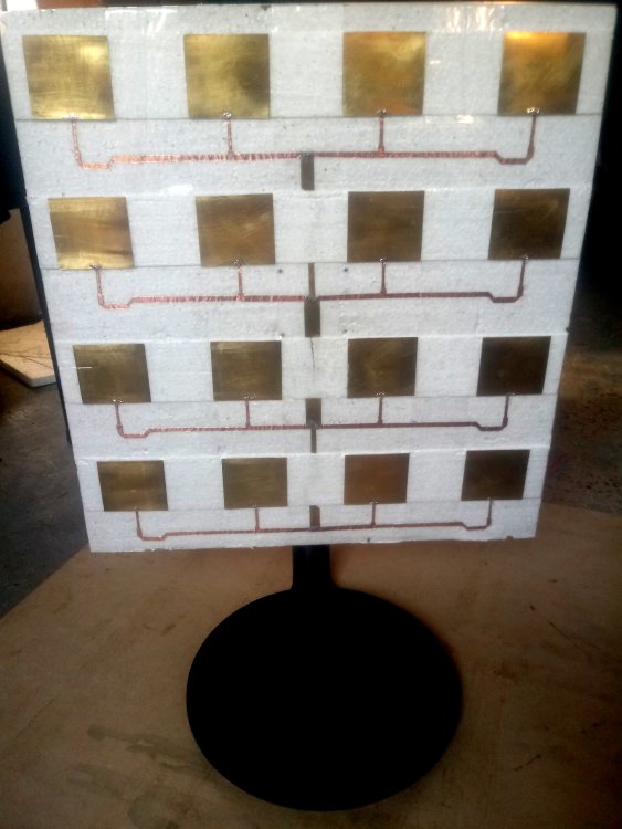
Feed network is at 2 mm from Aluminum Reflector , Patches are at 4 mm from Reflector...
There's a "tendency" these days to believe that Laser cutting-3D printing and AESTHETICS are a key factor...FALLACY
Energy doesn't care about aesthetics it only Flows were possible , mm or single degrees error don' make much of a difference
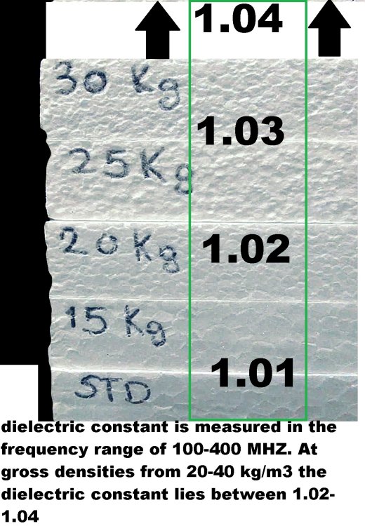
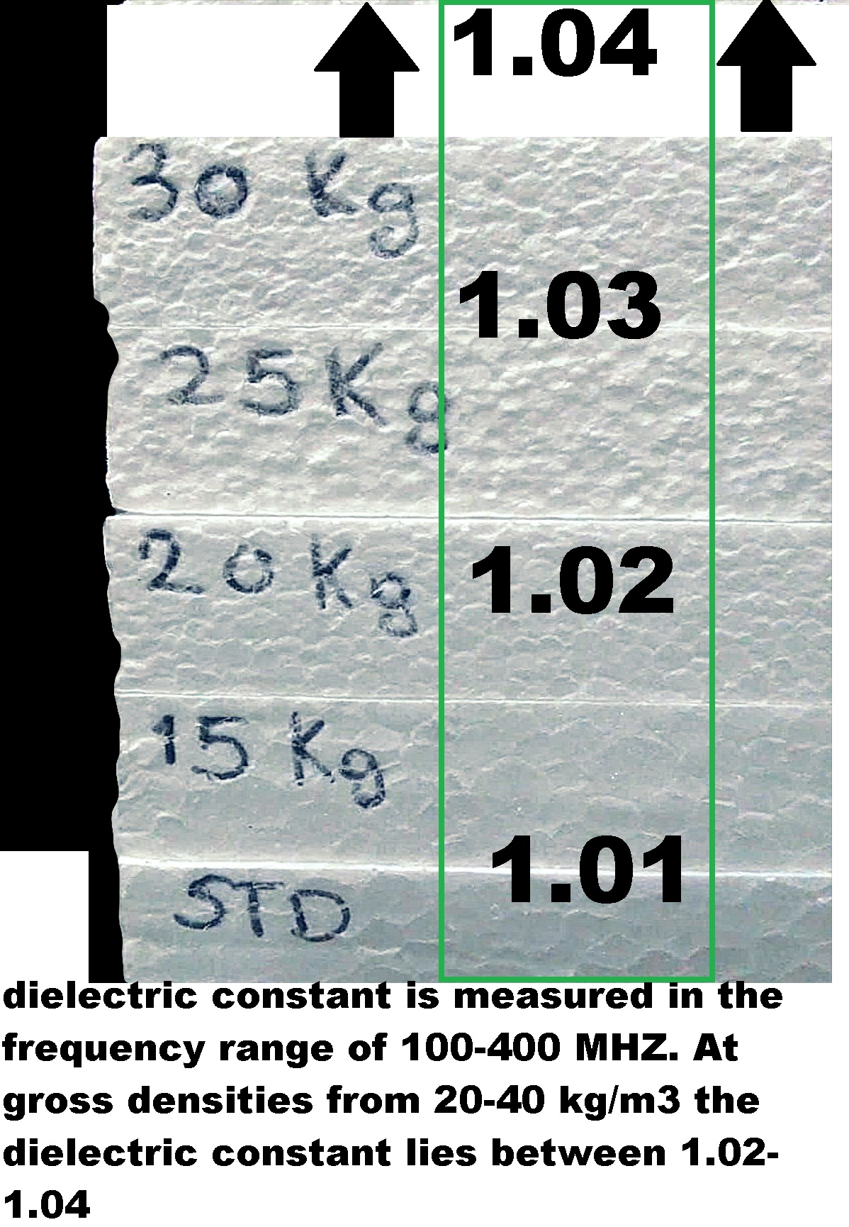
BUT dielectric Constant MUST BE KNOWN...to get to the ballpark.
-
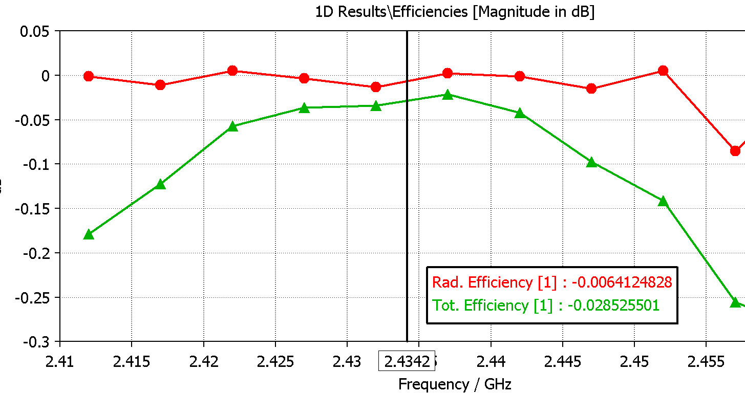
Efficiency of Polystyrene foam ...is unbeatable...
More losses on metal than dielectric...

-
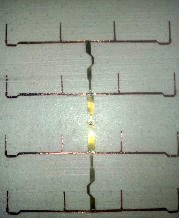
Brass 0.2 mm (patches and Central Feed) , Copper Tape (0.0254 mm) feed branches
 1 person likes this
 -
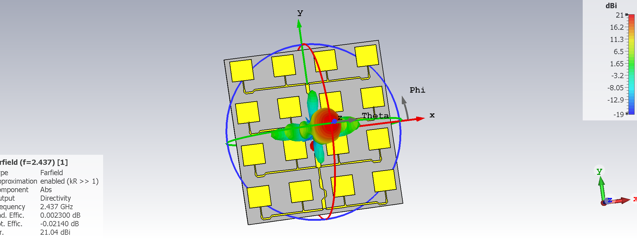
Been beating around the bush for years to find a Good 4x4 patch array...
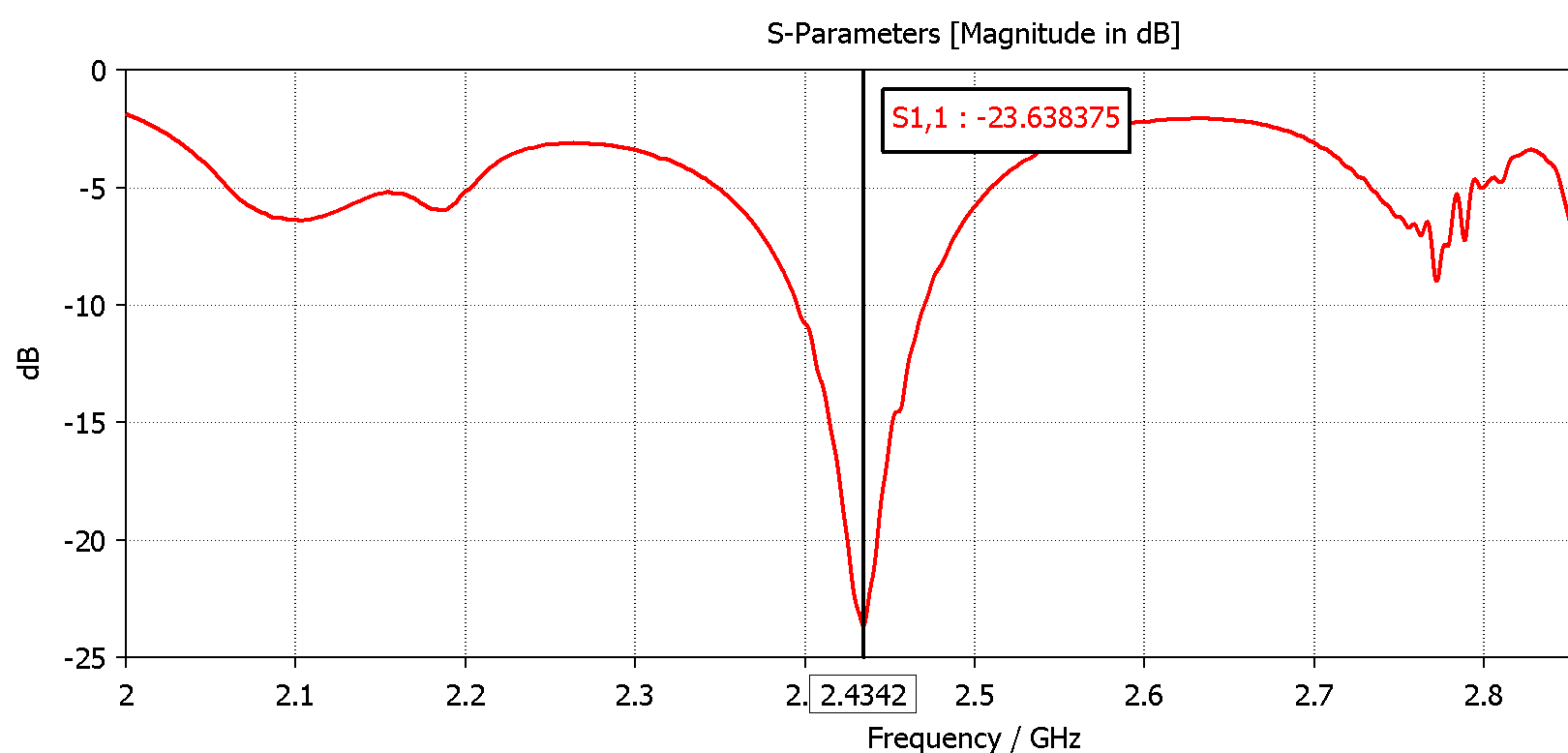
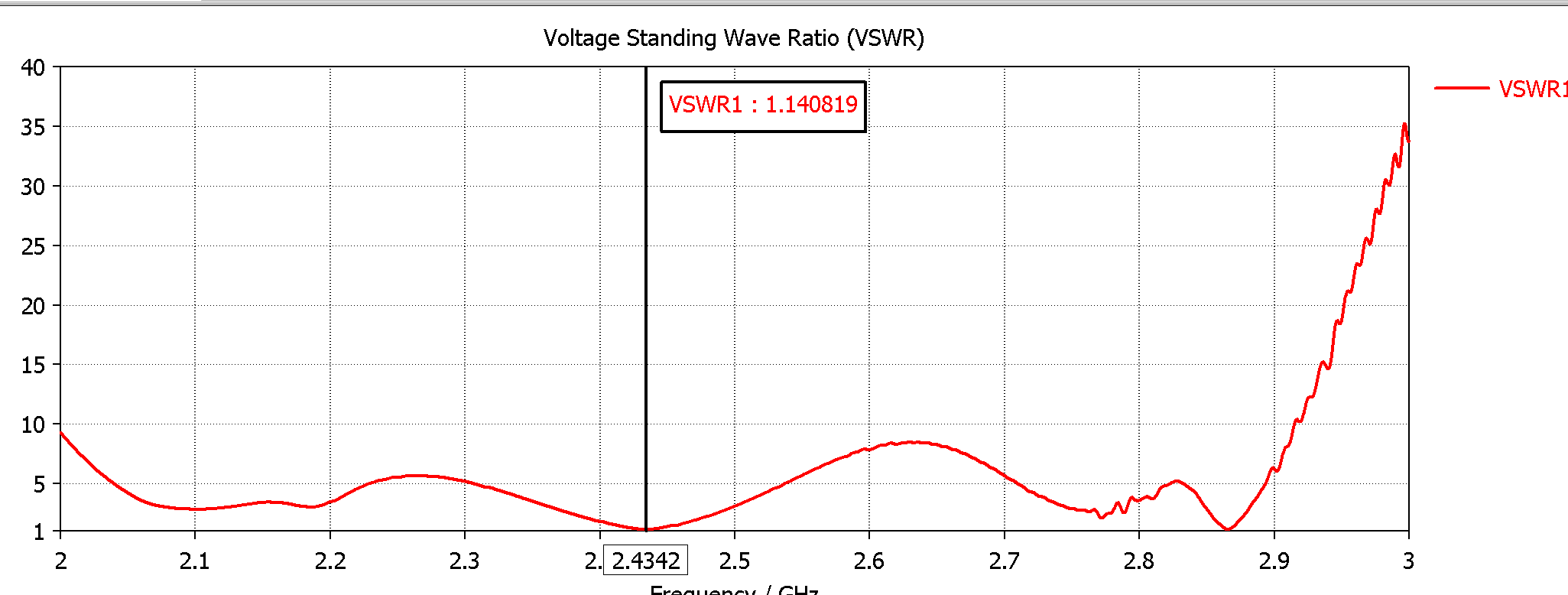
Higher than 21 dbi , good impedance through the whole band,low enough vswr, under -20dbi side lobes...
the original design is for 12,5 ghz and almost none side-lobes Power distribution Ratio 1:5:5:1
Changed it to WiFi , distribution ratio 1:1:1:1 (Original design Eliminated Sidelobes at the COST of 1,5-2dbi of gain)
I'm happy (some testing still needed )
REAL dielectric constant of Polystyrene foam is a guess (1.02-1.05)


 1 person likes this
 -
REFLECTOR SIZE ! (and SHAPE) that's where the 17 dbi come from...
-
-
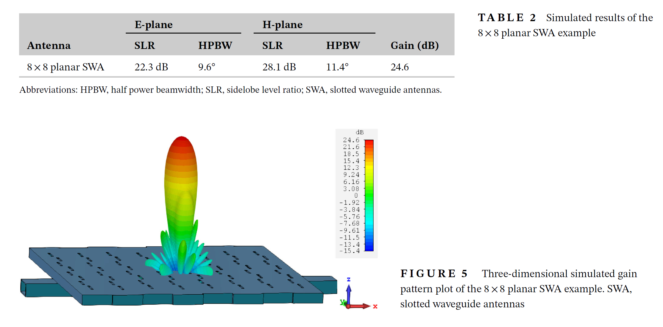
Polarization of slots is 90 degrees OPPOSITE of that of Lineal Dipoles-Monopoles , etc...
Vertical slots = Horizontal (lineal) Polarization
Horizontal slots = Vertical (lineal) polarization
PS: equivalent to a Magnetic dipole due to Electric field energy on slot's borders...
2 people like this -
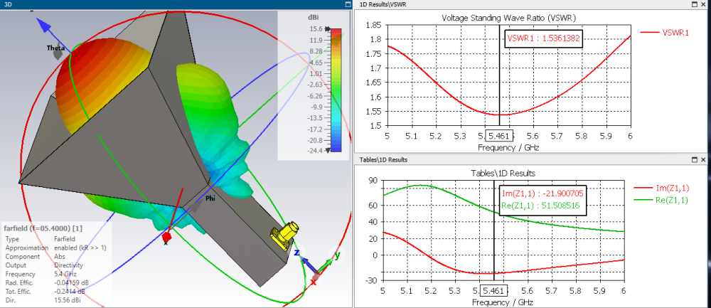
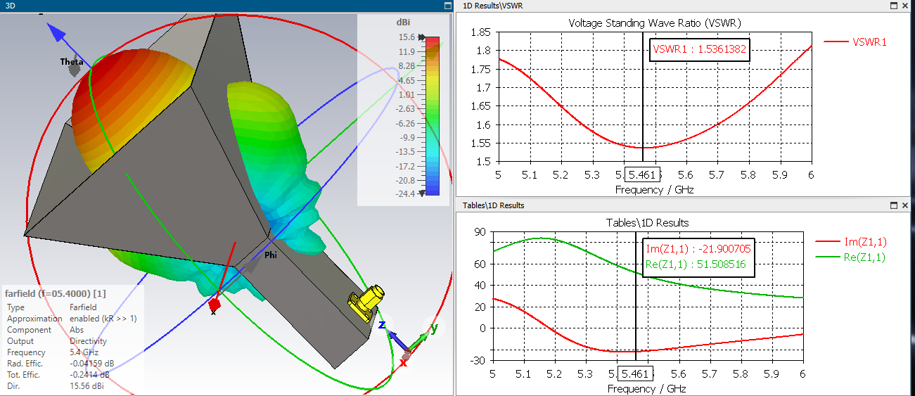
On 11/10/2023 at 9:21 AM, Admin said:Hello everyone.Here are proven horns for offsets at 5.4 Ghz offset 60cm .
Monopoles are highly CAPACITIVE (too short) with the cone shape maybe gets closer to 0...reactance ?
2 people like this -
On 9/3/2022 at 9:45 AM, fdag2 said:so if F=10.8mm what about the feeding point ? do I need to shorten the distance there and if I do what will be ?
and also I haven't done any balun's til now so what will be the length if I use RG58 50ohm.
IT only WORKS witha 4:1 BALUN (200 ohms at feed point BALANCED)
it is a GREAT antenna (i build it and i am USING it right now) over 18 dbi


in Antennas for mobile communications
Posted