Register now to gain access to all of our features. Once registered and logged in, you will be able to contribute to this site by submitting your own content or replying to existing content. You'll be able to customize your profile, receive reputation points as a reward for submitting content, while also communicating with other members via your own private inbox, plus much more! This message will be removed once you have signed in.

clanon
Members-
Content count
844 -
Joined
-
Last visited
Posts posted by clanon
-
-
thinking about 15dbi or more by adding a reflector...Sectorial...
-
-
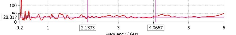
On 11/22/2024 at 3:10 AM, Pupe said:I tried to simulate the antenna in cst, but for some reason the resonance turned out to be shifted, all the dimensions were repeated exactly.
DIELECTRICS usually , radome adhesives...All add up in this case sustracts...
1 person likes this -
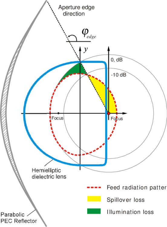
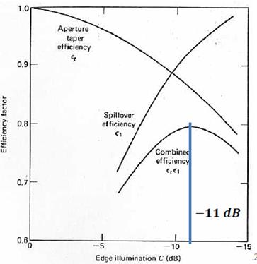
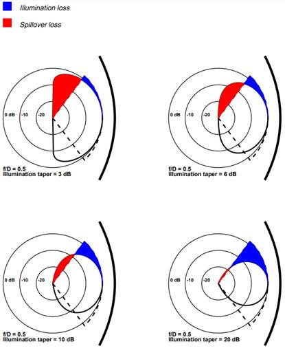
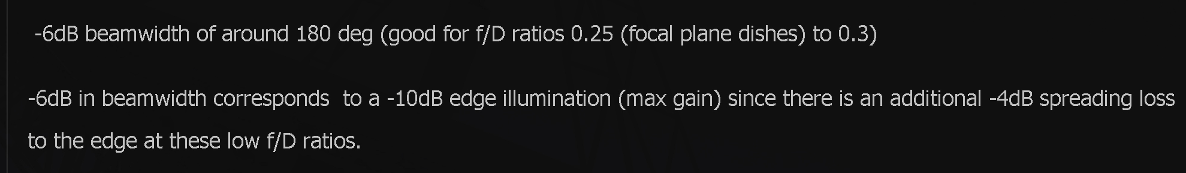
10 db is when losses are at minimum for both Spillover and illumination...
-
I think he means -6 db lobe pattern guarantees good efficiency for shallow dishes (with -4 loss at the border)

-
The shape of the main LOBE IIRC at -6 db affects efficiency...
1 person likes this -
On 11/14/2024 at 4:41 AM, Admin said:Clanon,could you give some dimensions?
-
-
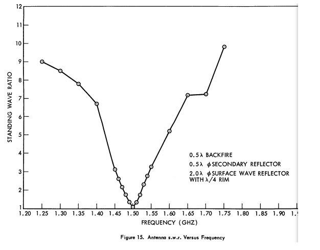
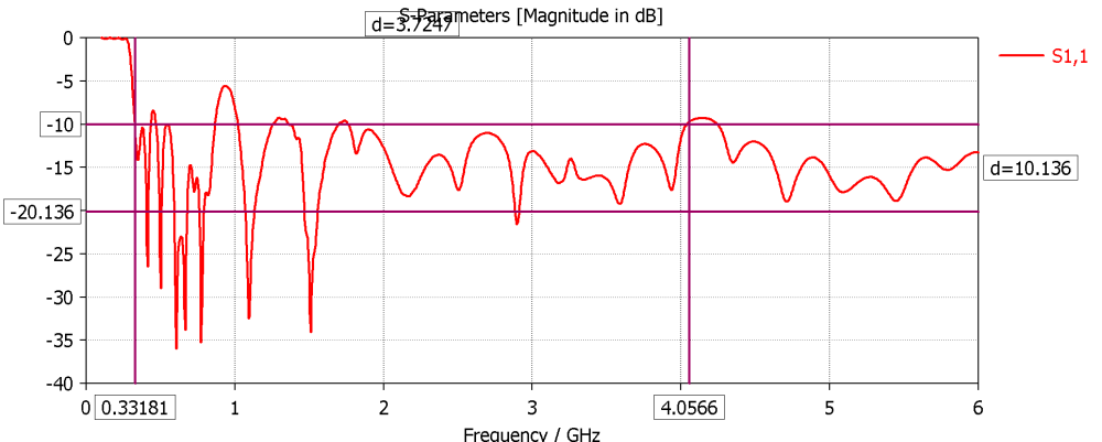
narrow band apparently
 1 person likes this
 -
Looks like you have a resonance , DEEP, at 2.8... try making the whole Yagi 1.16 times bigger...
-
1 person likes this -
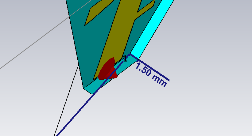
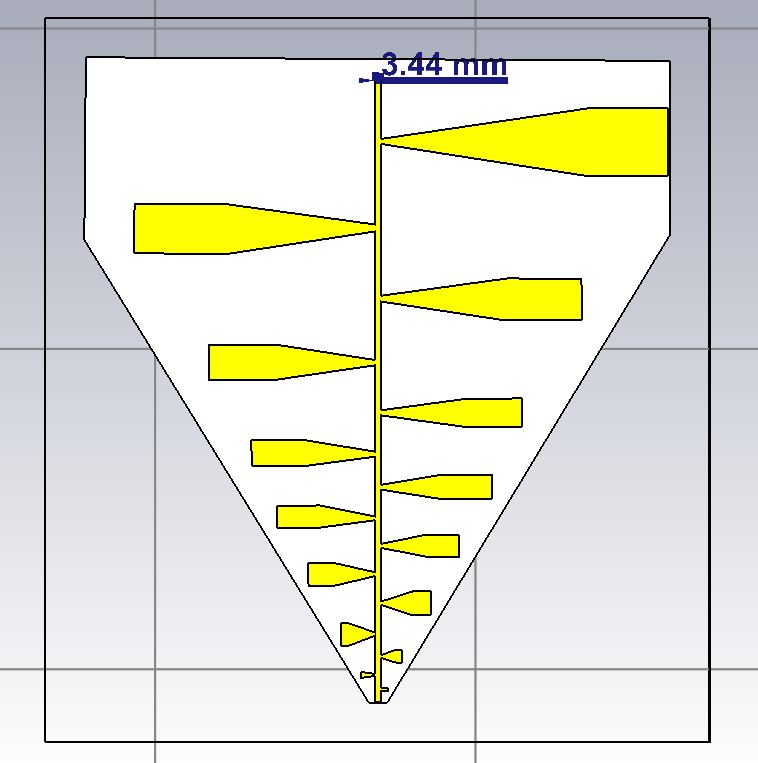
Feed line on FR4 needs to be THINNER 5 mm or less...to get 50 ohms...

 1 person likes this
 -
1.5 mm distance between sides (Feed Line)
-
Should I try with FR4 double sided PCB ?...(it must work but HIGHER LOSSES...maybe z would change...tho) Tomorrow i confirm it...
-
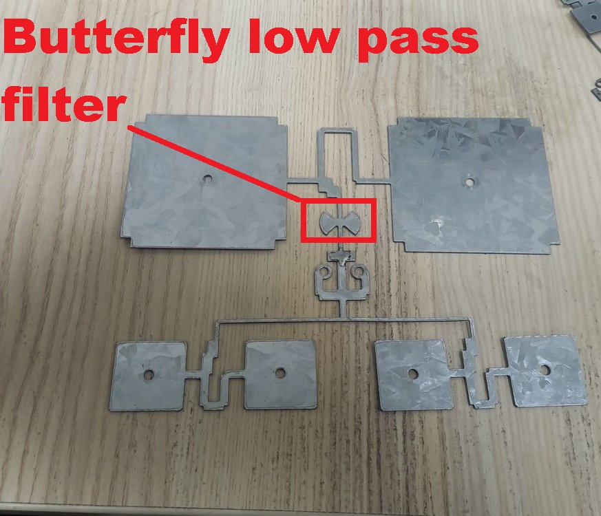
DXF , easier...TWO and a bridge in the back...+ CST (2019)
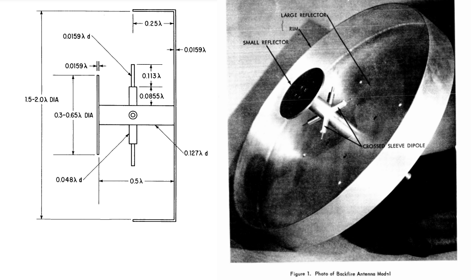
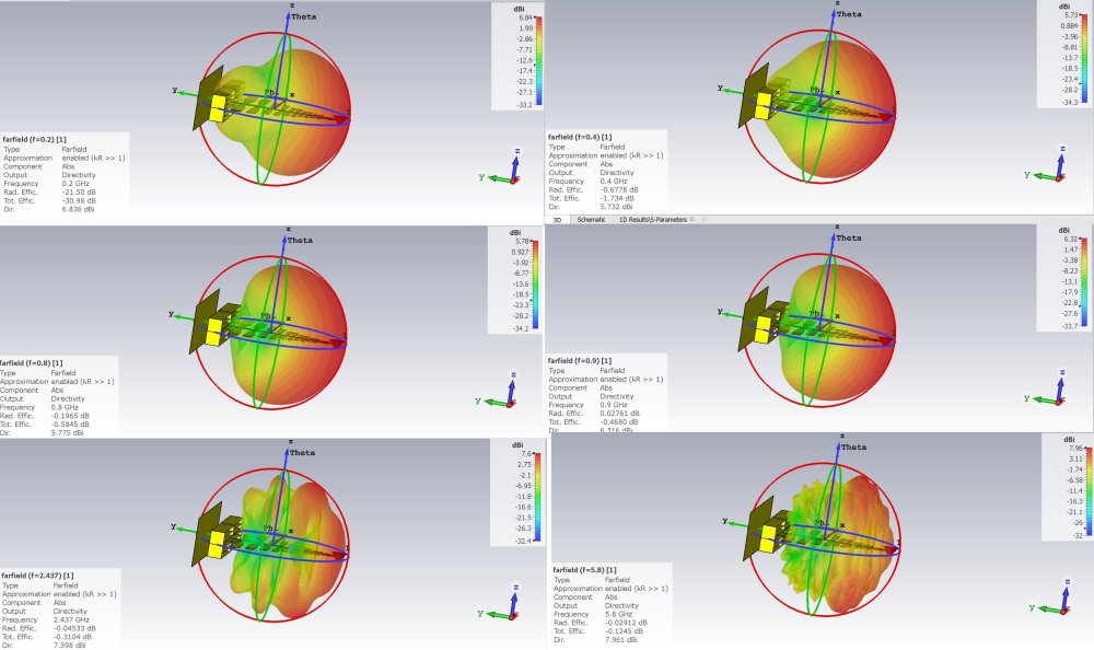
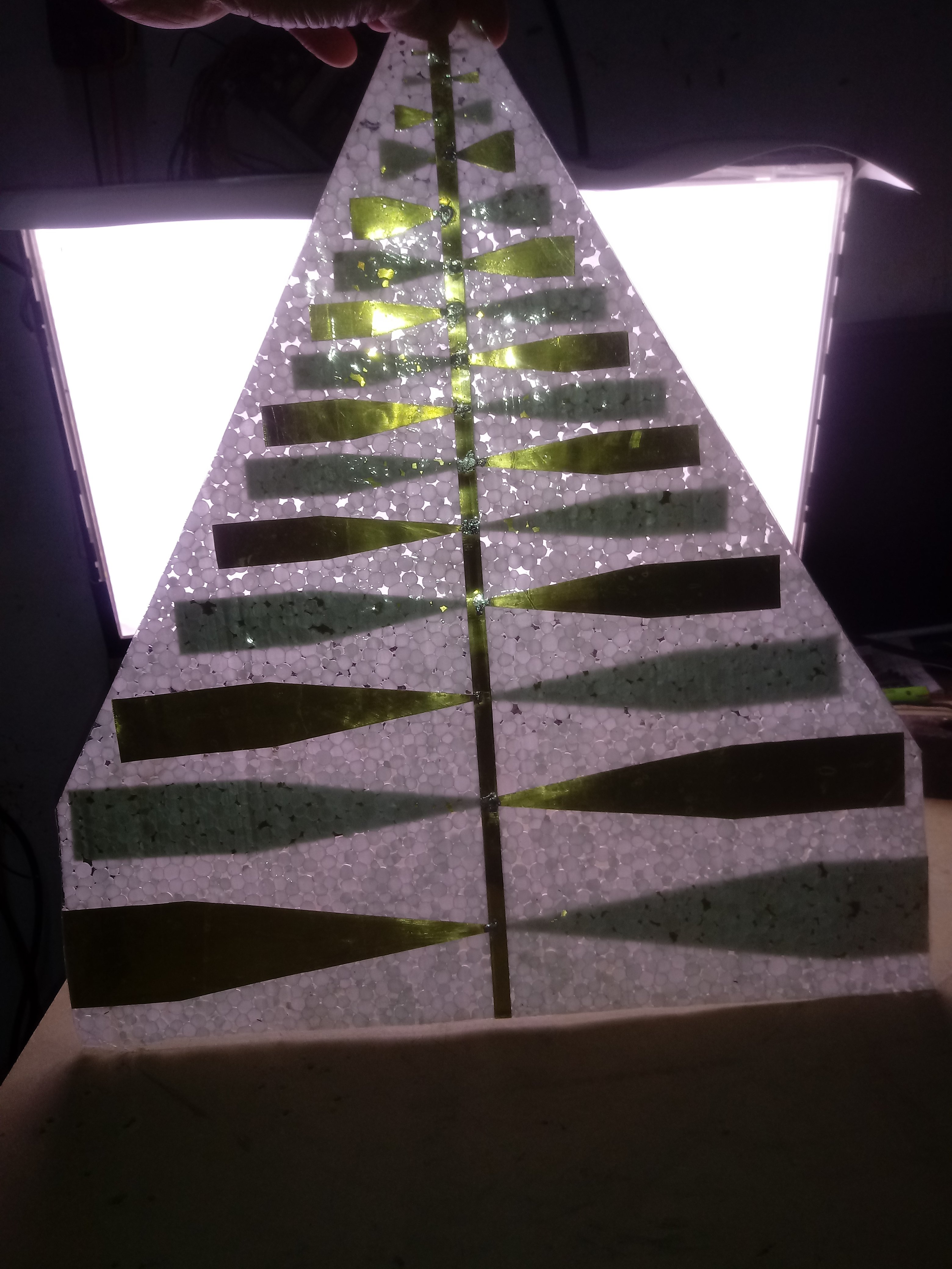
The one on the picture has a LOW FRECUENCY enhancement (200mhz) and a REFLECTOR PLATE some 10 cm in the back
 1 person likes this
 -

 2 people like this
 -
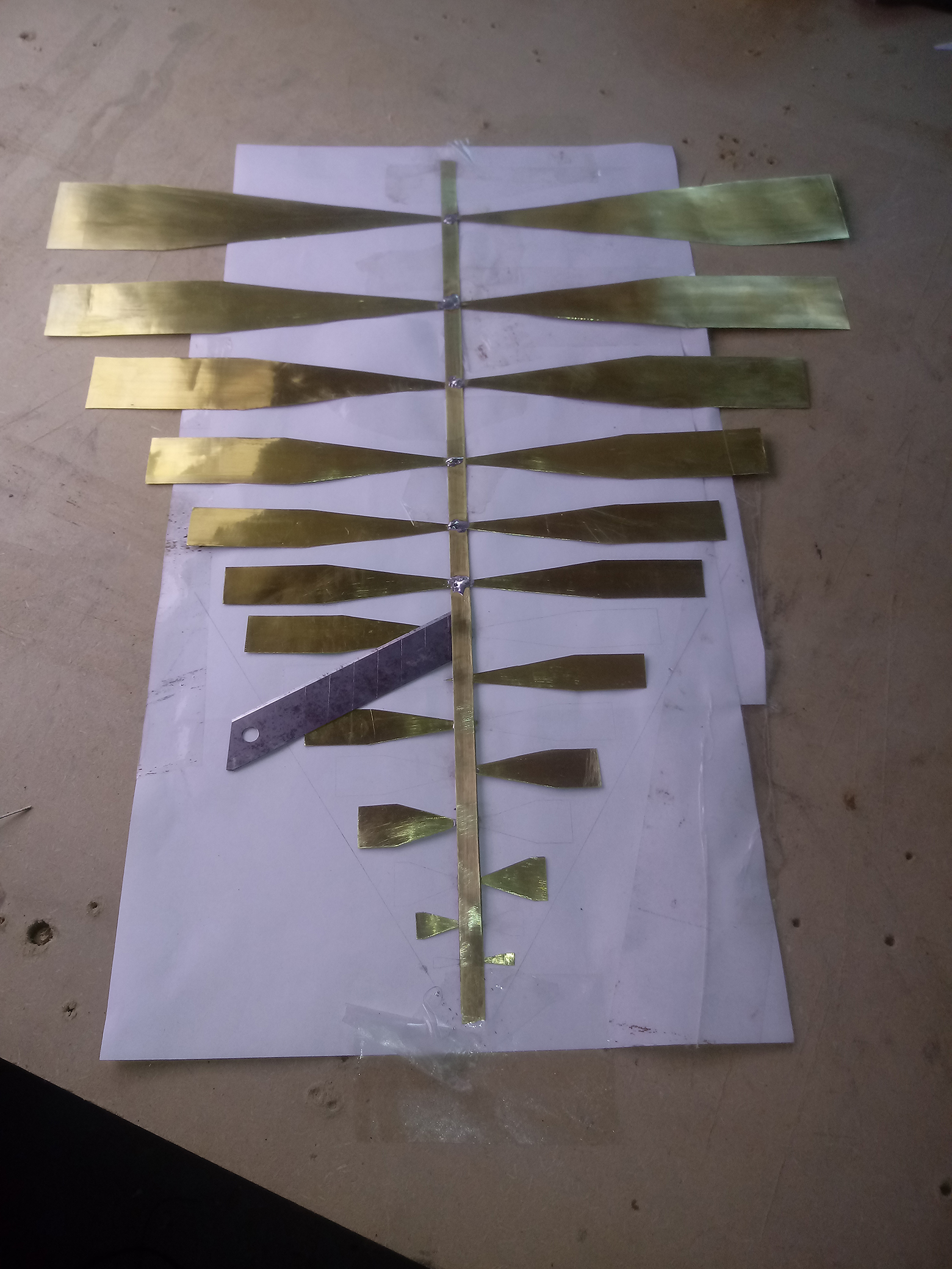
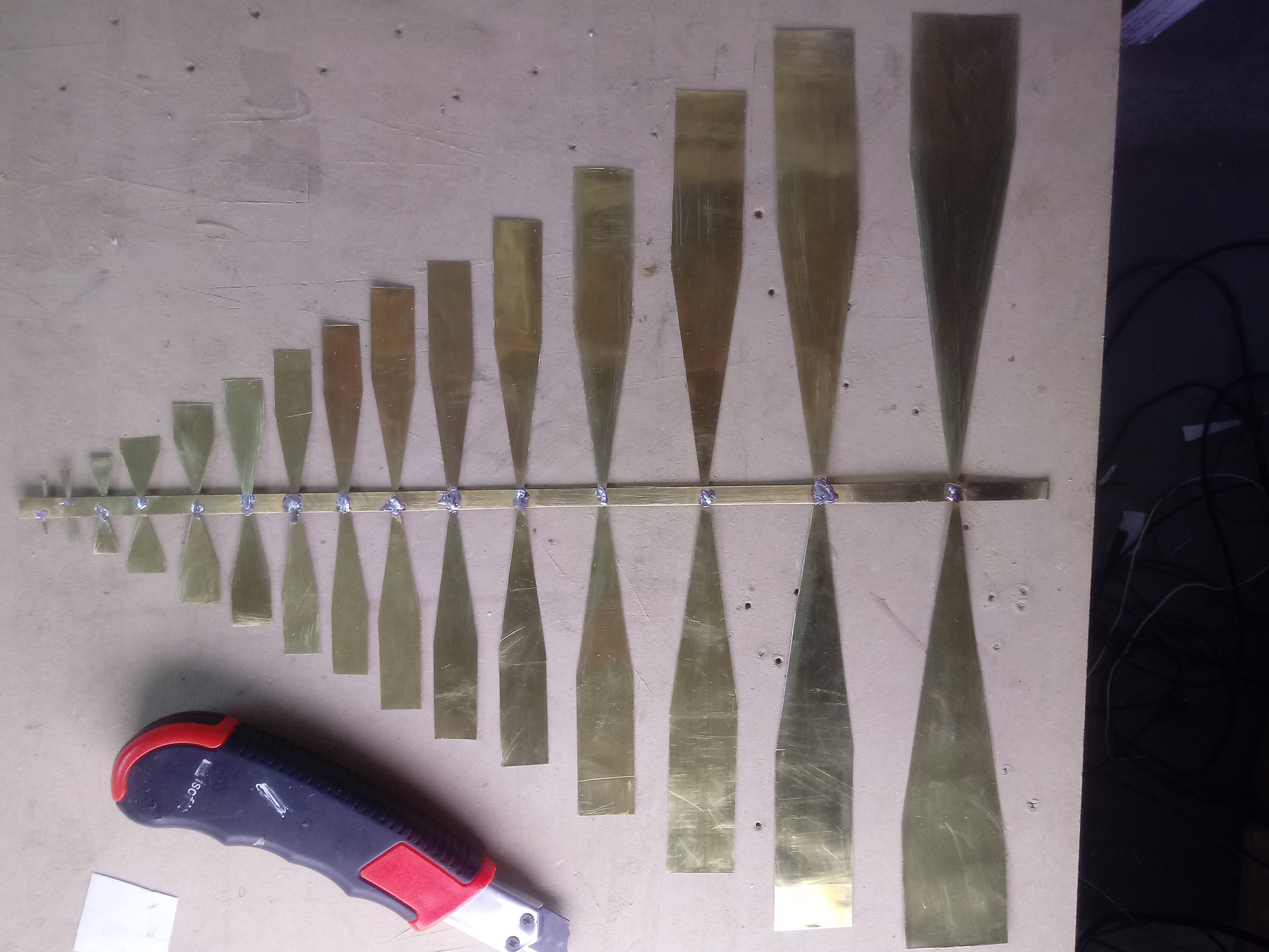
0.1 Brass sheet (can use ANYTHING you have)
1 person likes this -
1.5-2mm PES dielectric...RG316 low loss cable...


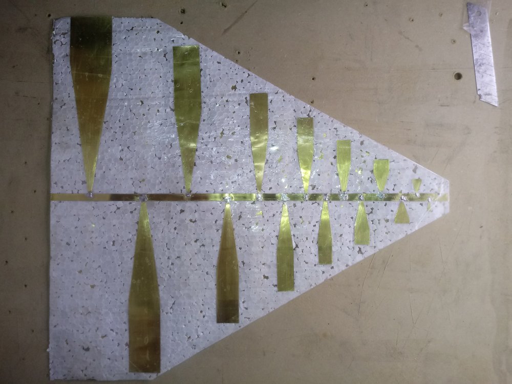
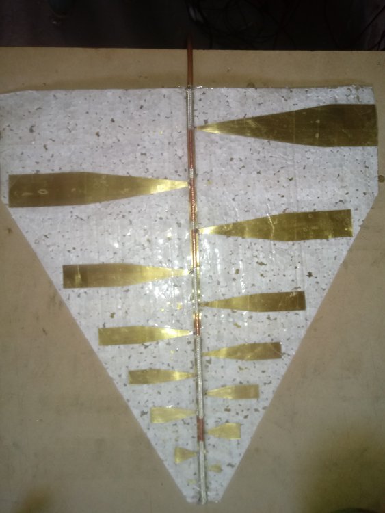 1 person likes this
 -
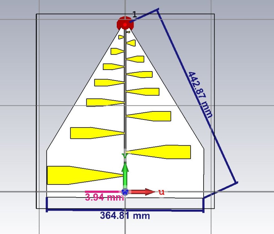
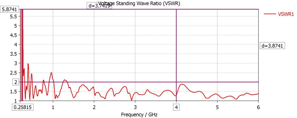
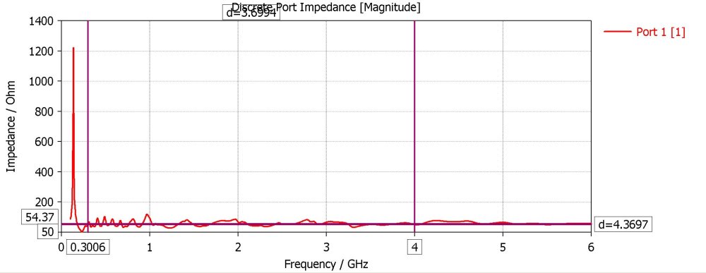
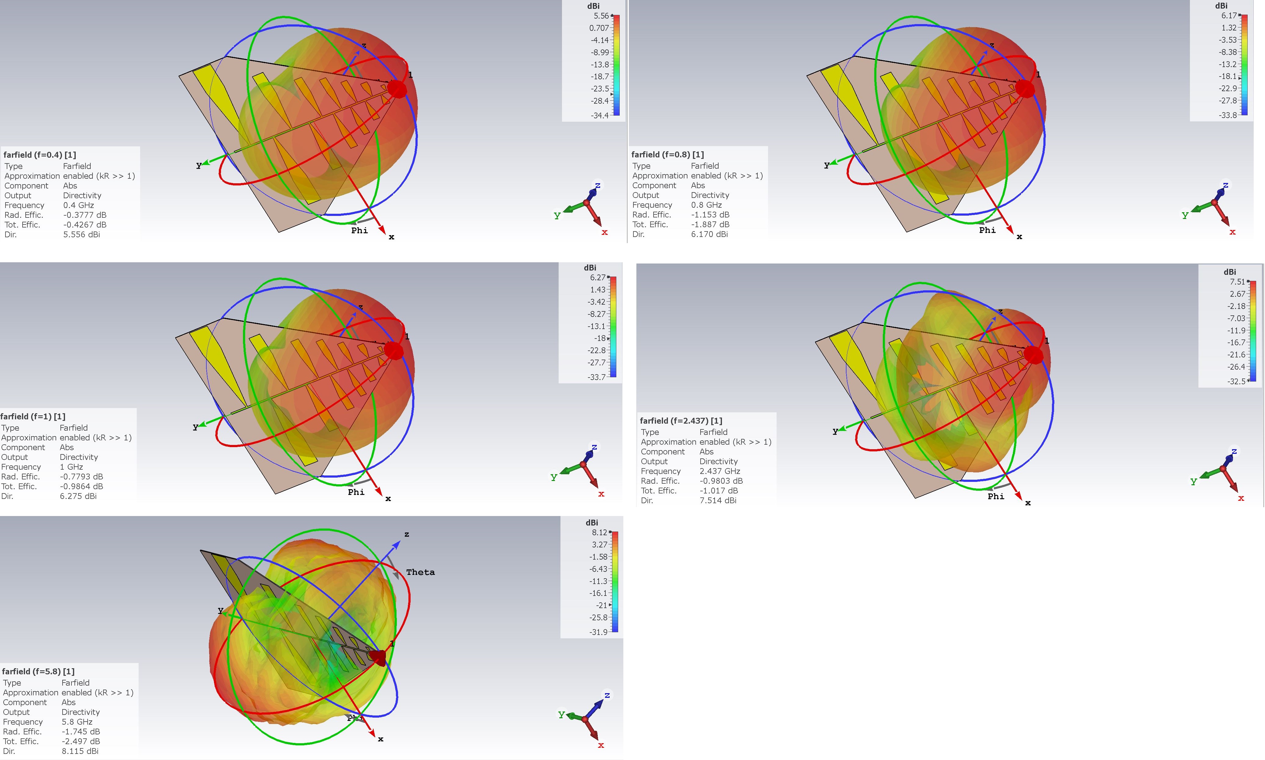
Trying to make a "GOOD" Lpda , SCIFI VIVALDIs from RFSPACE have NO GAIN (under 1GHZ) , Chinese LPDAs have LOTS of LOSSES and mismatch...50 ohms FLAT ALL band , just a peak close to 1ghz unavoidable on this antennas...

 2 people like this
 -
10 hours ago, ALecNET3993 said:This is slightly off topic but could you link me to some resources or books thought which i could learn how you guys are able to come up with the dimensions for this type of disc yagi antennas? Is it just trial and error or do you use any equations?
https://www.vinoth.org/rf-calculators/circular-patch-antenna-calculator
trial and error but several curves for director reflectors are well known ...NEED to run several SIMULATIONS , tho
2 people like this -
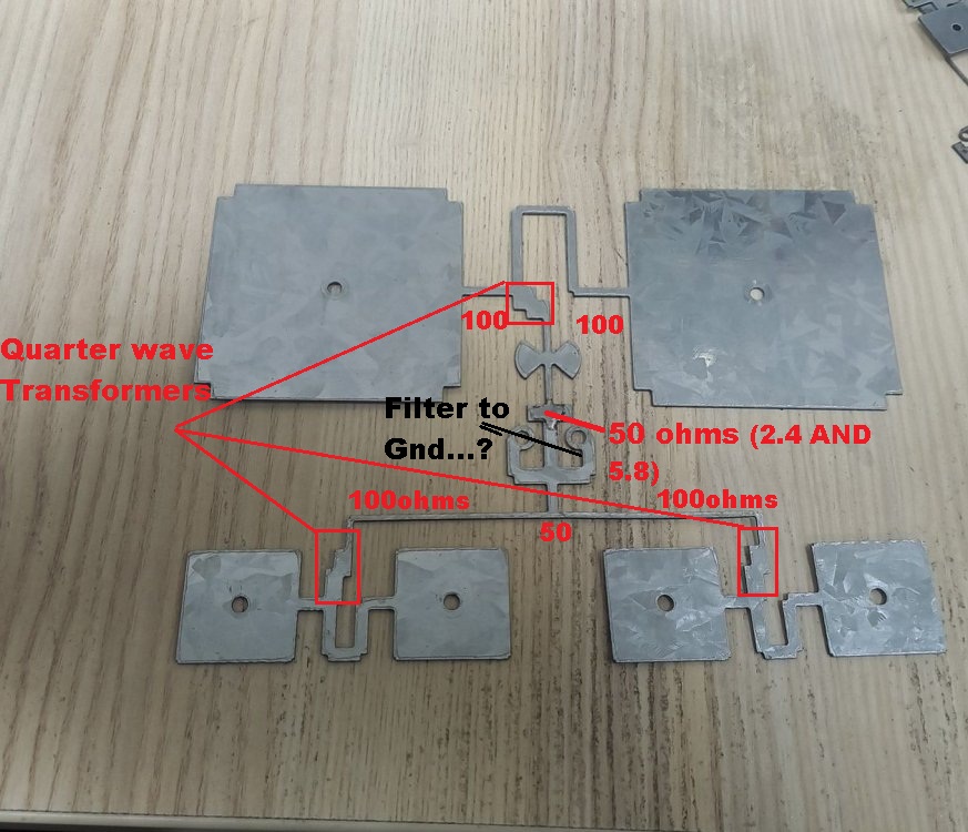
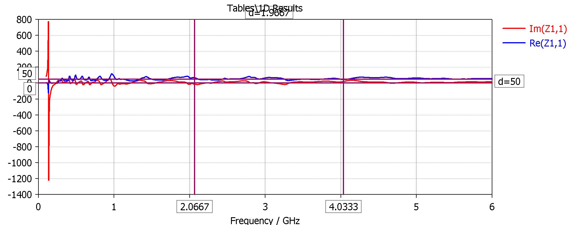
put the Feed lines close to reflector (2mm or less) and patches where they are and REACTIVITY and VSWR should get BETTER ! jomi
-
Think of each Patch as Resistances , since you have 4 patches for 5.8 and two patches for 2.4...(and YOU NEED to end up on 50 ohms) cutting in a half doesn't work for ALL patches...Filters add complexity (BUT adapt impedances to EACH BAND)
 1 person likes this
 -
2 hours ago, AmateurRadist said:After 10 failed attempts I think deviding was not good idea, so friends just use antenna as it is, hope above information will be useful to someone thanks
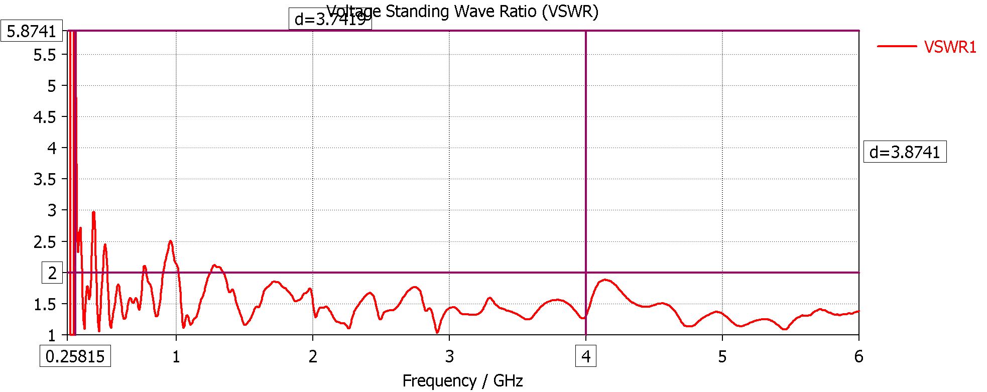
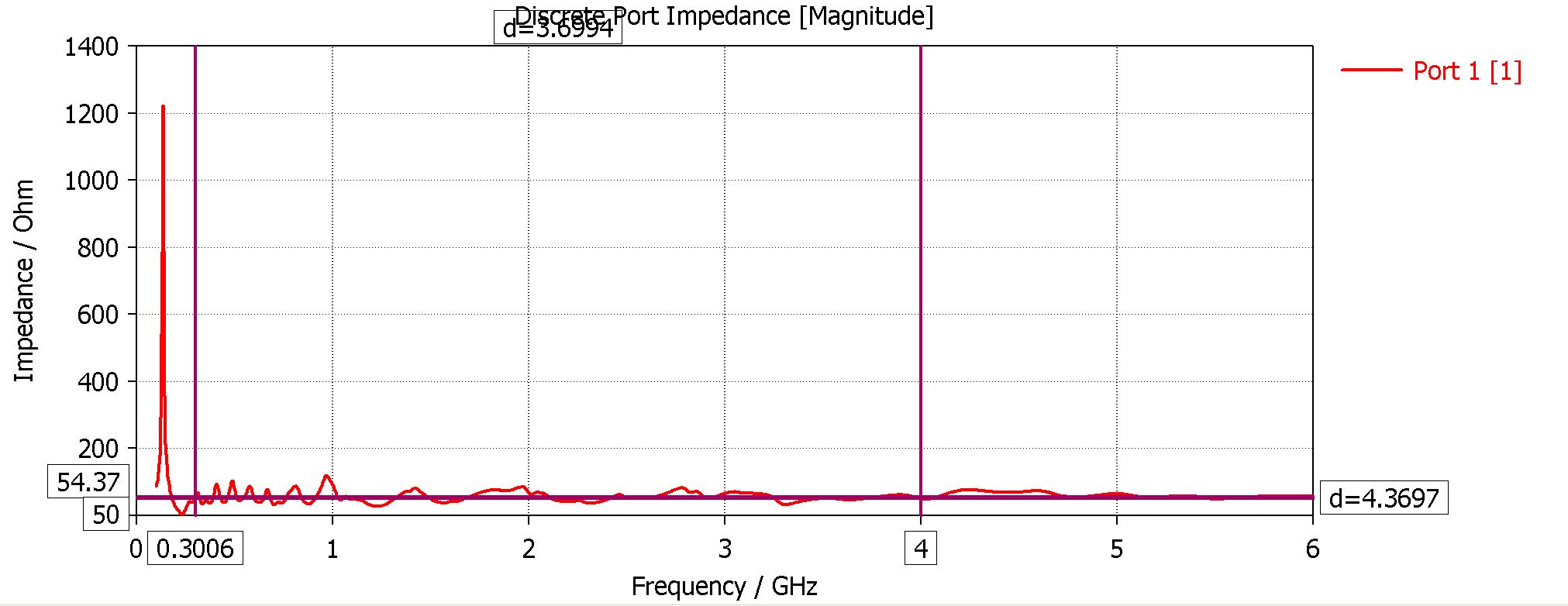
The final impedance resonance vswr s11 , have the WHOLE as target...imho
-
 1 person likes this


in Antennas for 2.4 GHz band
Posted
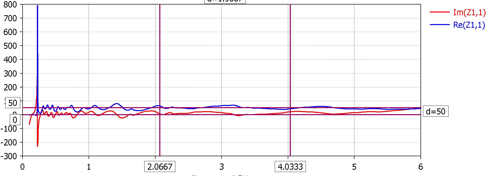
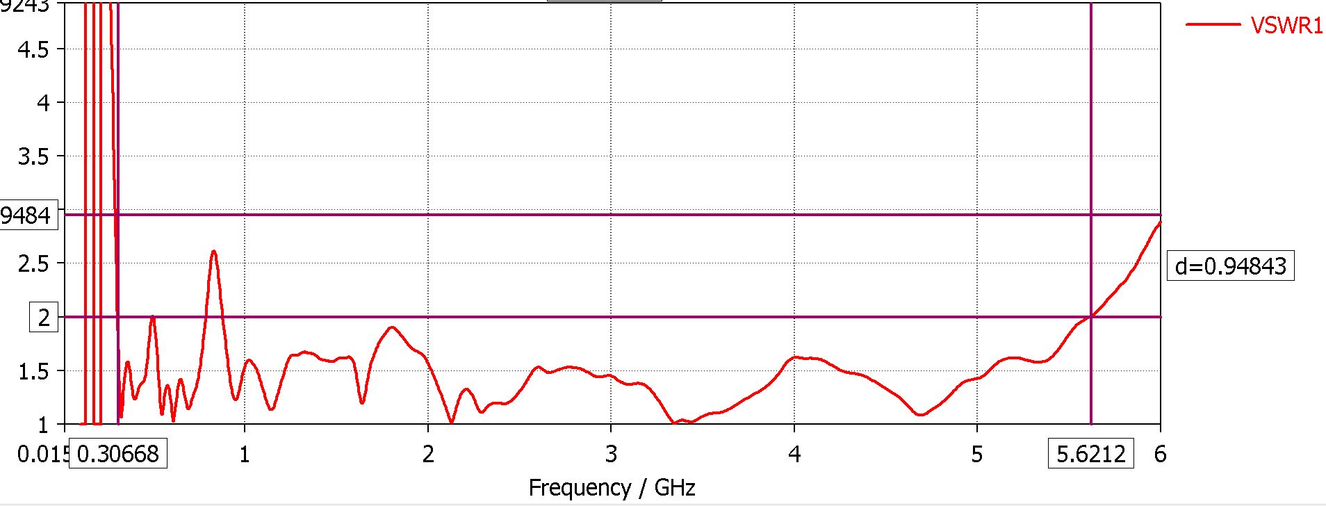
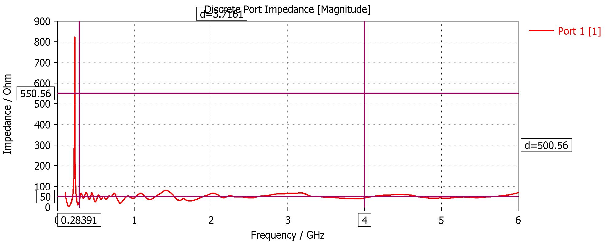
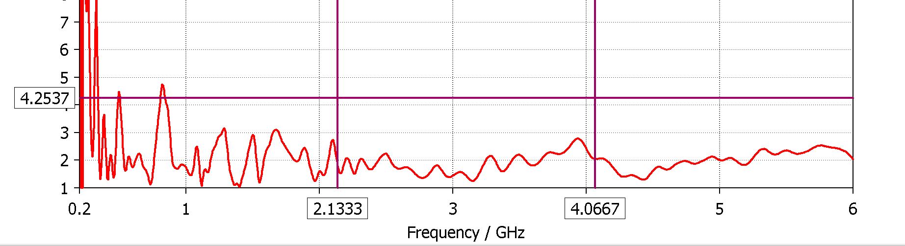
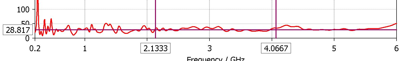
Different SOLVERS give Different Center Frequency (Frequency vs Time Solvers)