Register now to gain access to all of our features. Once registered and logged in, you will be able to contribute to this site by submitting your own content or replying to existing content. You'll be able to customize your profile, receive reputation points as a reward for submitting content, while also communicating with other members via your own private inbox, plus much more! This message will be removed once you have signed in.

Harry36
Members-
Content count
179 -
Joined
-
Last visited
Posts posted by Harry36
-
-
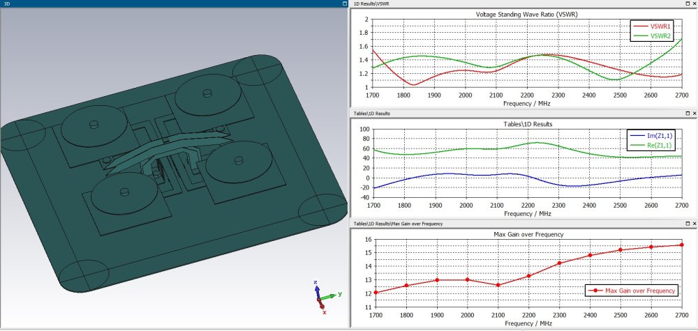
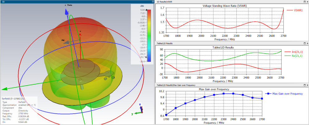
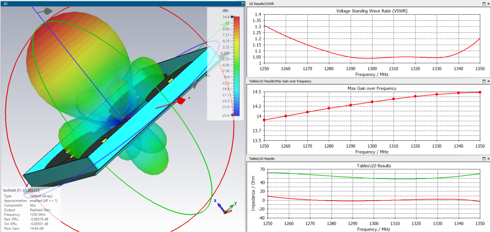
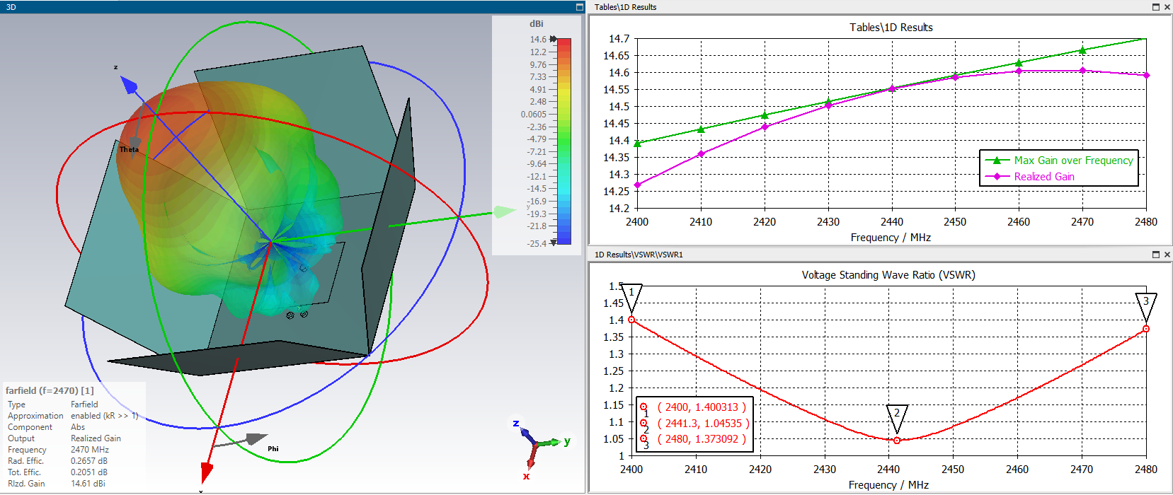
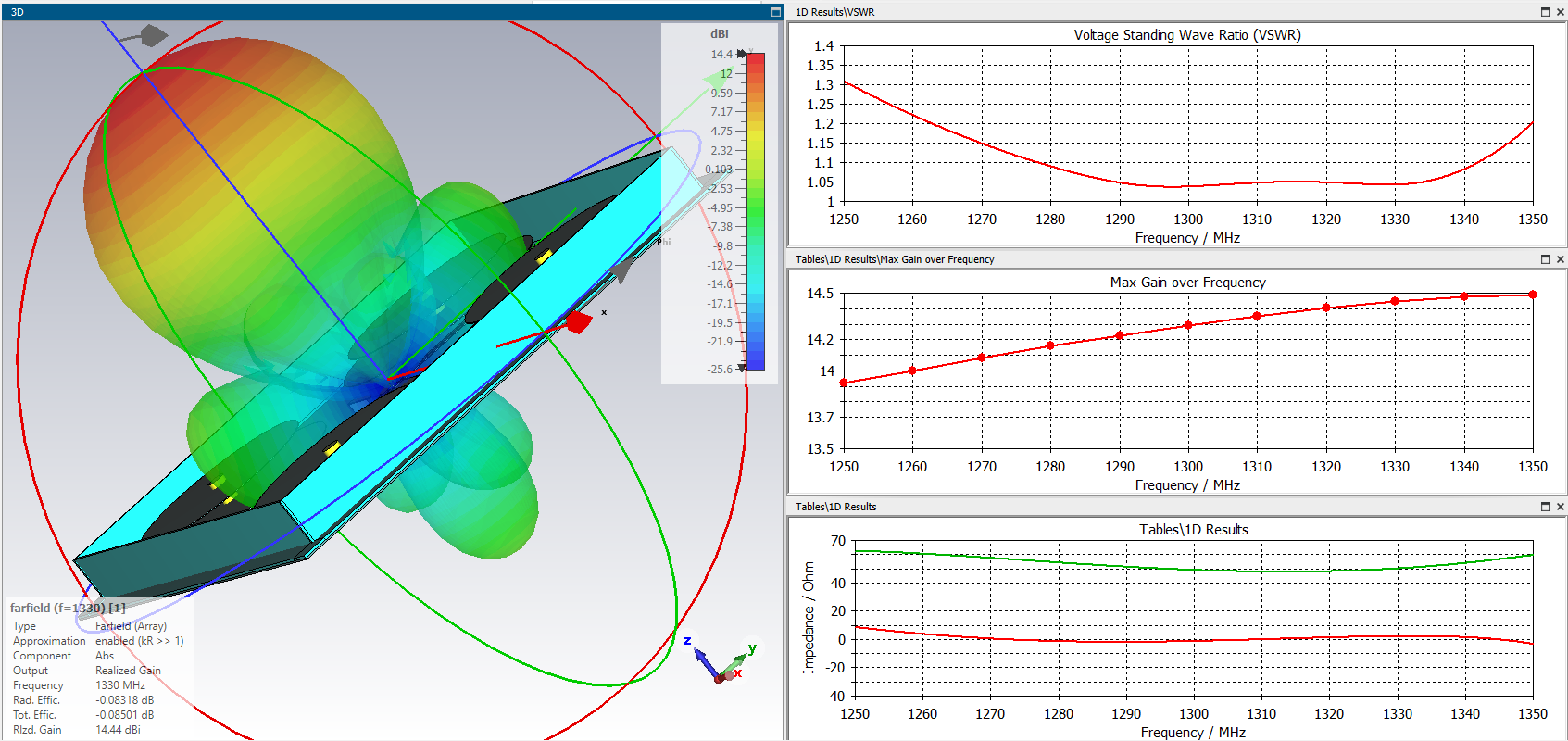
12 hours ago, Dr. Pepper said:I found some motivation and tried to add a balun to the design to see if this works and with some calculation i found a solution:
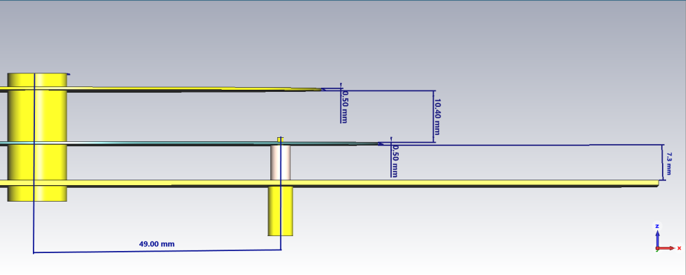
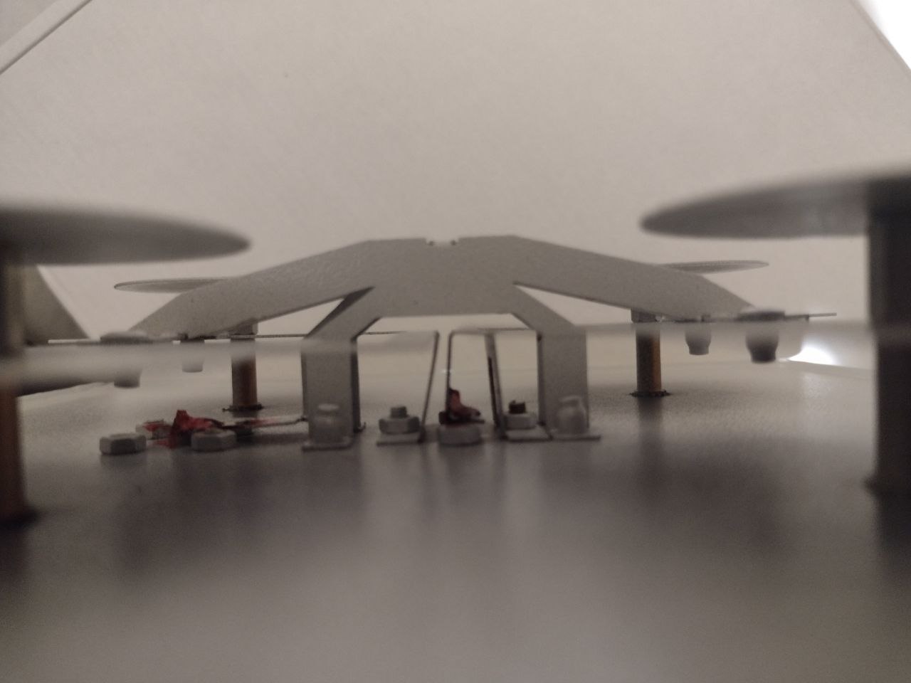
Side view (without legs to get a chance to look inside):
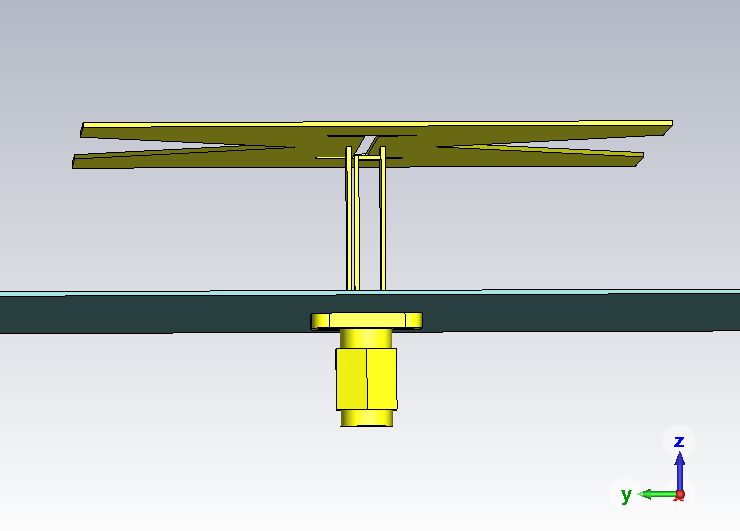
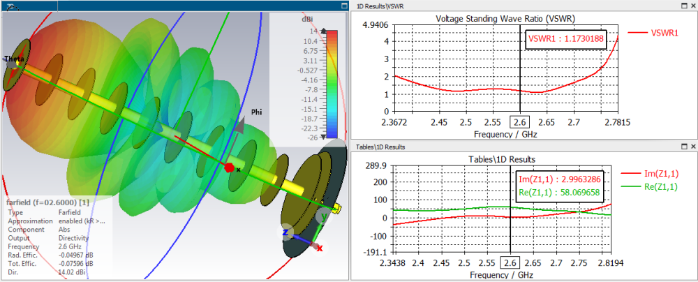
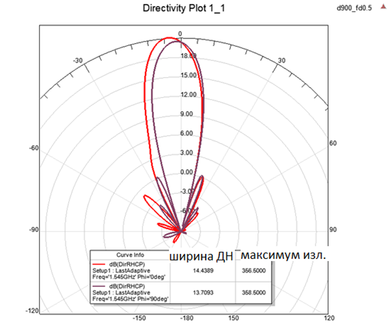
woks quite good, good broadband behavior and a good gain of 14.6 dBi. Its a bit like a batwing antenna
A good start! It remains to choose the sizes to expand the band 1700-2700. Once you do, I’ll give you another good idea.
1 person likes this -
On 22.11.2021 at 4:30 PM, Harry36 said:outdoor kna27 kna27-800/2700
without plastic protection

 2 people like this
 -
8x16...Small gain... should be 30dbi ~30 dbi
-
-
On 3/16/2023 at 4:34 PM, Admin said:,,,and this works just as well...
 On 10/3/2021 at 1:00 PM, Admin said:
14 dbi - very well?
1 person likes this -
18 hours ago, miloudsatdz said:What is the tool used for cutting?
Use ordinary metal shears for cutting. use a drawing compass for marking.
what was recommended to you by the message above applies to cutting ceramic tiles or plastic. when cutting metal with such a tool of metal sheets, very serious injuries can occur. do not use such cutters!
-
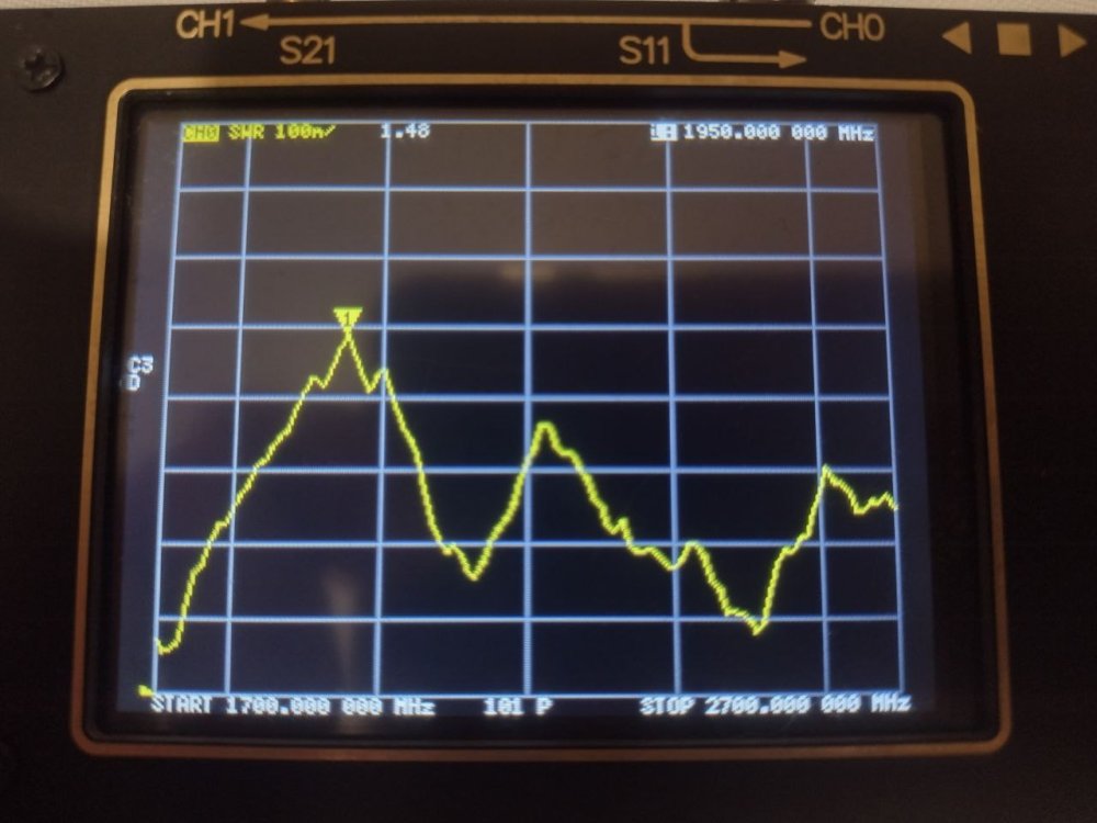
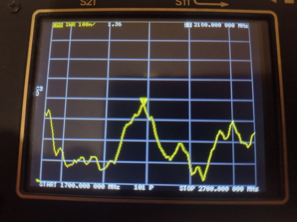
34 minutes ago, Admin said:,,,and with ARINST Measuring equipment, something completely different comes out...!!!
without knowing the size and method of feeding, it is not necessary to talk about it.
-
7 minutes ago, Admin said:300 MHz...???,,,, the frequency bandwidth is rather large...!!!!
1800 - 1700...1900
2100 - 1900...2200
500 MHz
But...

-
10 hours ago, farad84 said:Hello. Who has the correct drawing with dimensions for bdm 1800-2100 mimo and 50 ohm cable?
bester did not produce such an antenna
-


.png.44191206357a1ffb466d7b3200c559b8.png)
 1 person likes this
 -
On 16.01.2023 at 5:10 PM, jbckdsav said:Here my small test similar result.
Whatever the shape of the emitters, we still will not get a single phase center for the emitter to place it in the focus of the offset reflector.
Leaving the focus of the phase center of the antenna will lead to a deviation of the radiation pattern beam from the main direction (this can be seen on the graphs: the beam deviates from the axis), this can be minimized by pressing the emitters to each other.
as soon as we start to press the emitters to each other, then the isolation between the power ports begins to fall.
if you carefully consider the article to which you refer, then on the graphs we will see the parameters S12, S13, S14. this is the isolation. she is on the verge of a foul. -10 is very little. the smaller the isolation between the power ports, the more difficult it is for the modem to parse the received signal. this results in slower speeds due to reduced modulation. There is such a document of one fairly authoritative organization in which engineers recommend having an isolation between power ports of at least -15 dB, although they say that it will most likely work at -8.
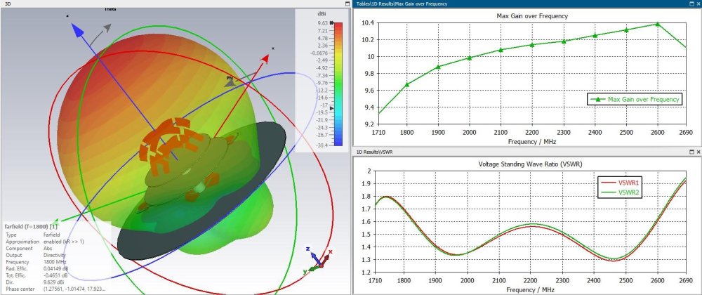
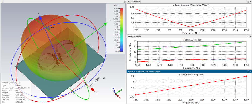
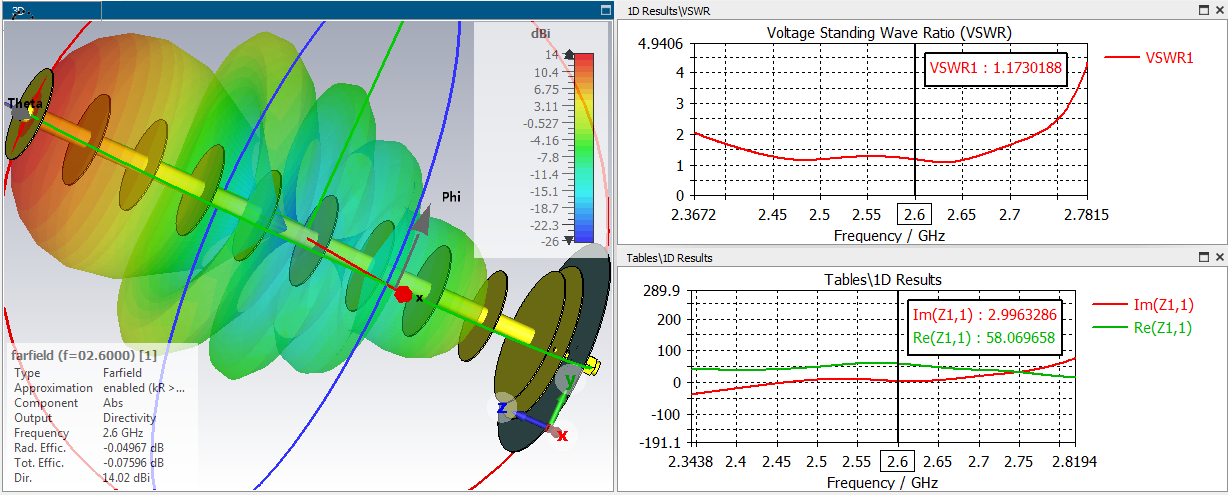
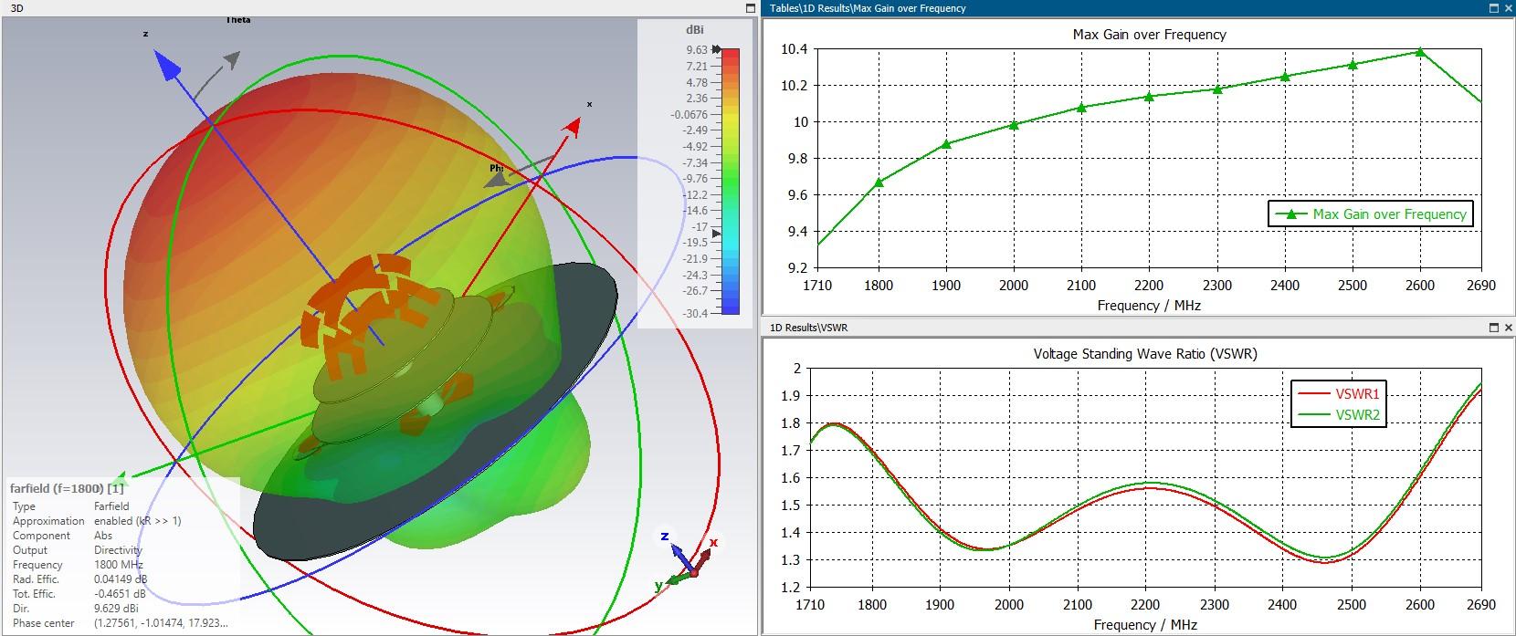
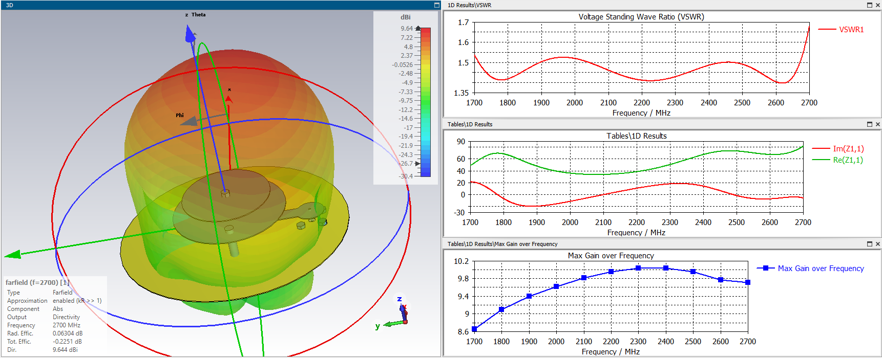
how it will work, they do not say. (fig.3)well done, nice simulation! but do not repeat the mistakes of other users. for the overall picture in the initial calculation, it is necessary to show other users the graphics: 1. gain - this will allow you to understand how the antenna behaves in the desired range. 2. SWR. this gives the concept of a matched antenna in the original band. the SWR graph should be displayed in the range, or a little wider, to show others the margin of the antenna. the graph is displayed from 1, not from 0, as some do. don't make childish mistakes. SWR cannot be less than 1. The output of the graph from 0 is an indicator of the developer's illiteracy. 3. radiation patterns, at the borders and in the middle of the range. this makes it possible to evaluate the distortion at different frequencies.
p.s.
you also need to understand that for different types of offset or direct-focus reflectors, you need to have different amplification of the irradiator.
for F/D<=0.5, the gain should be about 10 dBi. for a ratio of ~=0.7, the gain should be about 12 dBi. these parameters are valid for any frequency and this is clearly seen from the factory feeds designed for different types of reflectors.good luck
") 1 person likes this
1 person likes this -
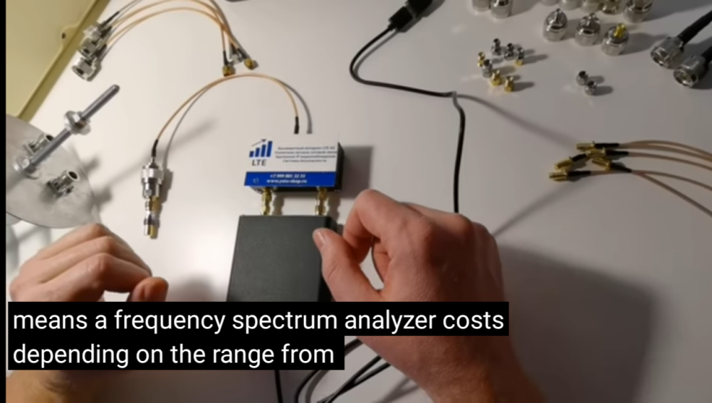
On 9/13/2021 at 4:36 PM, Admin said:open a video on YouTube, turn on subtitles and turn on auto-translate into English. In fact, the author did not say anything normal in this video. he has very little knowledge. this is a simple seller who does not understand anything about what he sells. in Runet, he is a laughing stock. one of his 28 dBi antennas has already become a meme.
 1 person likes this
 -
PetraBB mimo 2x2 50 Ohm
version 2020


-
-
 2 people like this
 -
Real 1/4 petra 9 4x4
 1 person likes this
 -
-
-
2 hours ago, Admin said:,,,what does cst2023 have in addition to the previous versions...???
https://www.3ds.com/products-services/simulia/products/cst-studio-suite/latest-release/
-
-
-
On 15.09.2022 at 1:35 PM, eco32 said:What else, what profit can it give.
.thumb.jpg.42c4ee633bb301bb0133545683c5801e.jpg)
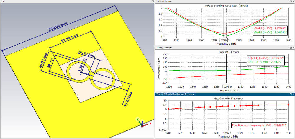
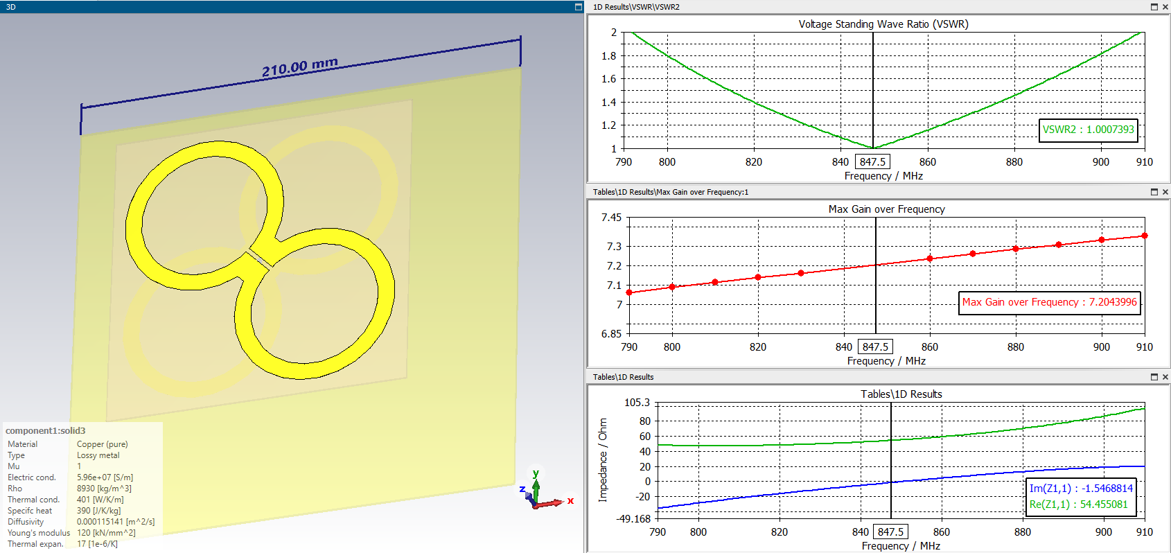
Figure 2 in the quote shows the dimensions of the antenna for LTE800 band (min swr~ 850 MHz), it is made in the form of two antenna sheets on different sides of FR4. the dimensions match the simulation quite well.
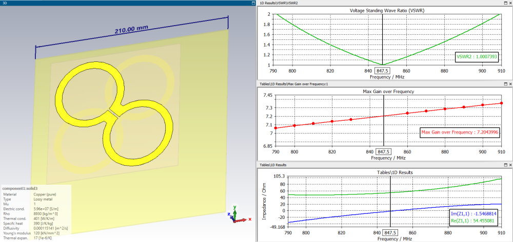
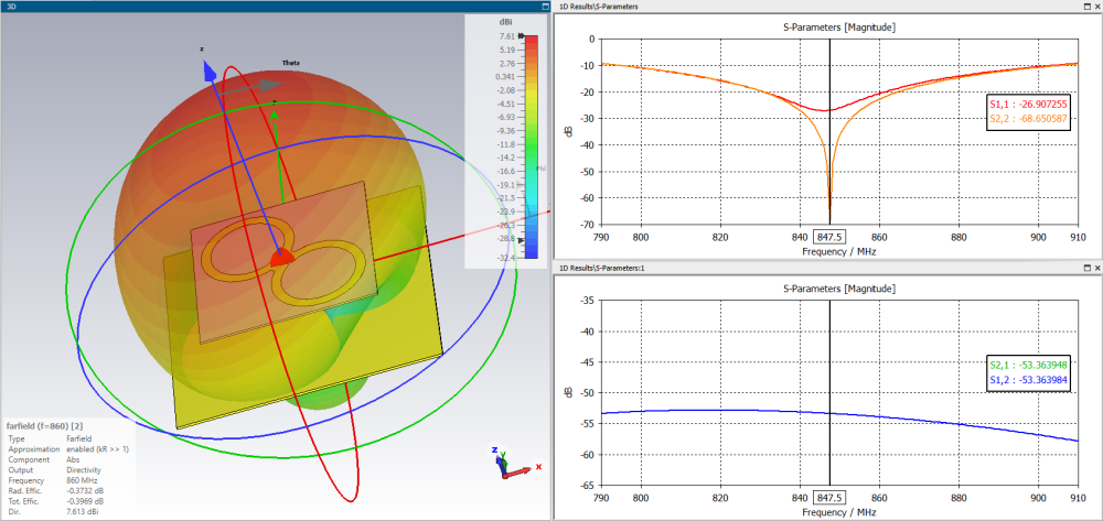
In order to make a similar antenna for a frequency of 1296 MHz, you need to reduce the dimensions by a factor of 1.52 dimensions.
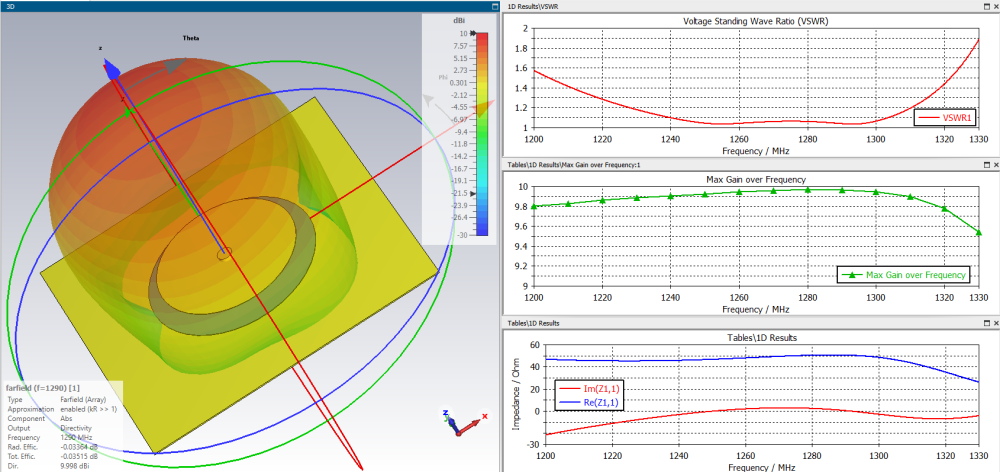
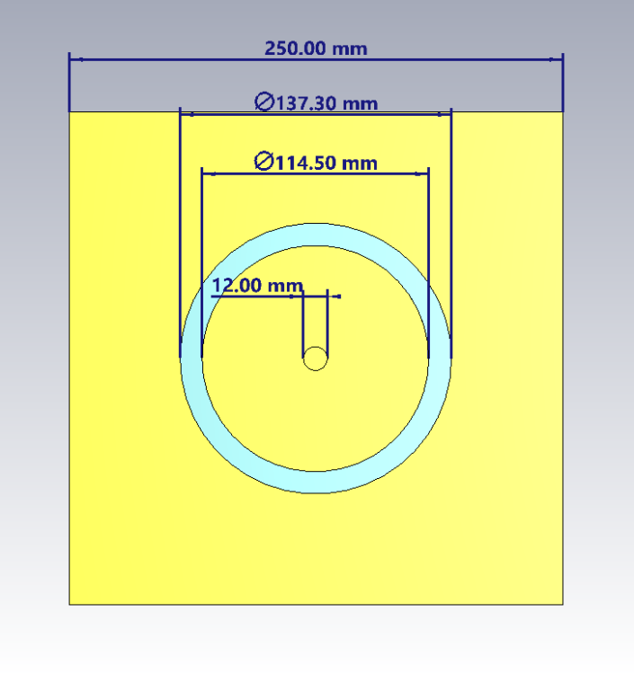
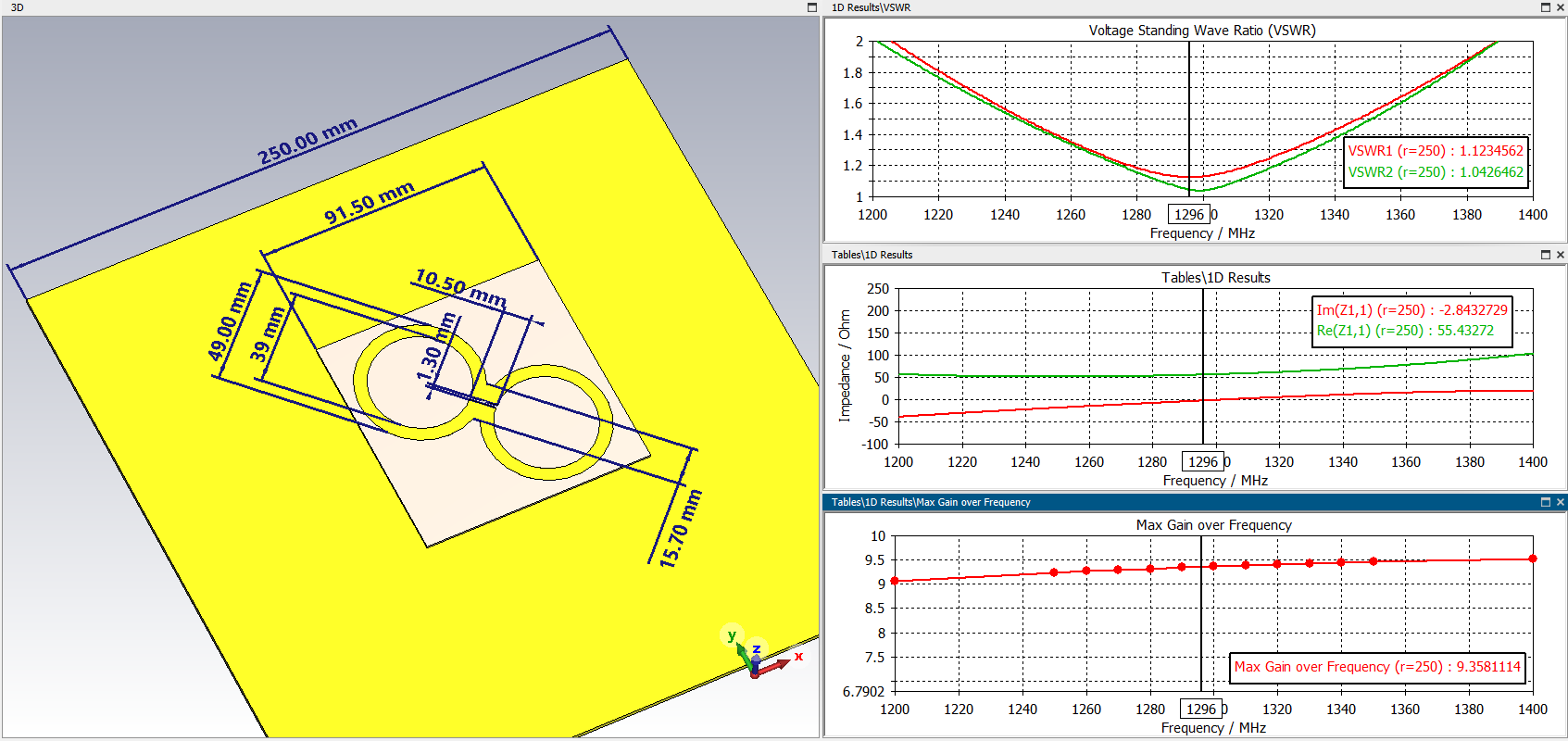
The antenna has a fairly low gain of ~7.2 dBi. This is due to the minimum size of the reflector. By increasing the reflector to 250x250 mm, you can increase the antenna gain to 9.5 dBi at the same time, if you do not change other dimensions, the SWR also increases to a value of 1.1. tFR4=1mm, tCopper=0.018, H=28.4.
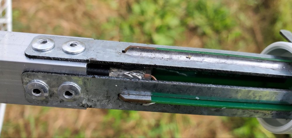
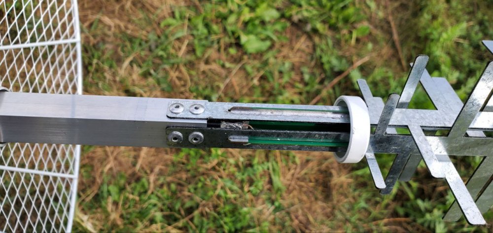
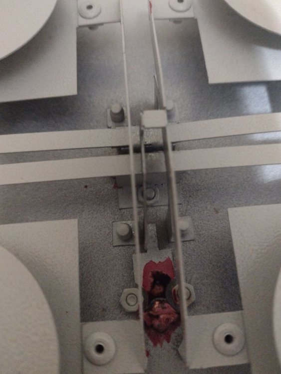
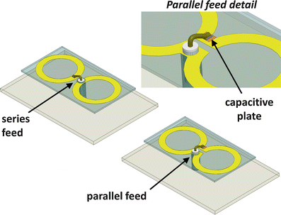
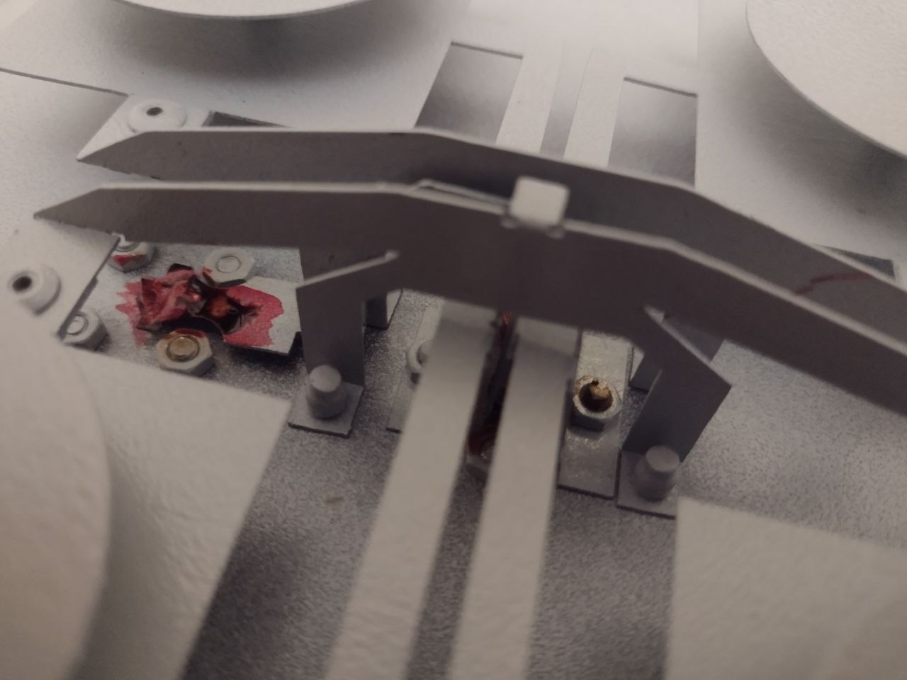
Antenna connection is shown in fig. 1 quota is performed without balancing, this is a wrong connection. The cable must be soldered from the side of the web of one of the antennas (upper or lower) and brought along the arc of a circle to the middle of the frame (circle), then lowered onto the reflector, where to install the connector. Cable use RG-316.
FR4 is a rather unstable material and antennas made from it very often fall outside the calculated range. for home production without appliances, it is not entirely suitable. it may be easier to make an antenna out of metal. For example, by type BDM. reflector and two disks. this will give a fairly wide bandwidth at a very low SWR and will forgive manufacturing errors even with a hand tool.
or stack 2x2
or dipole from metal can dia=66.3 mm
 1 person likes this
 -
7 hours ago, Admin said:,,,it is also possible like this, circular dipole...
It's not dipole, this is biguad + balun )
-
19 hours ago, Dr. Pepper said:The slot dipole with V cut outs like an batwing antenna, not as good for broadband application but a little more compact than the slot dipole and a good gainer. Here an example for a wifi antenna
Try to draw a balancing device in the model.
1 person likes this


.jpeg.a2e3dd70b1aed51c1b9127716db31101.jpeg)
.jpg.470cb116edfb1b3d38e6d37bc9695387.jpg)


in Antennas for 2.4 GHz band
Posted · Edited by Harry36